Battery Charging Problems
#1
 02-20-2010, 01:02 PM


Join Date: Feb 2010
Posts: 6
Likes: 0
Received 0 Likes
on
0 Posts
I have a Yamoto 150 that is not charging. The rectifier/reglator was cracked and smoking a little bit so was definately faulty.
Using information elsewhere on here I checked the stator output and this has two white wires feeding the rectifier. One runs at 22-24vac and the other at 28vac when running at about 2000rpm.
The existing rectifier/regulator has 4 wires. Red to battery. green to earth and then a pink one and a yellow one which connect to the two white wires from the stator. The problem has being to find a regulator with the same combination of wires and so I have ended up with one with five wires, Red Green Pink and yellow and an additional black wire.
When the wires are all connected as before and ignoring the black wire which meters out as an earth wire ( direct connection to the green), run the engine and hey presto the battery is charging BUT at about 18.1 vdc.
Could this be a faulty regulator as it is causing the battery to fizz and will no doubt damage it in the long run. Or have I made a mistake in the wiring up. I have seen a wiring diagram for a 5 wire regulator that shows the fifth wire running the auto choke.
Our quad originally had a auto choke but we have converted it to manual choke which solved the original starting problems which would suggest that the choke was not working but was never connected to the original regulator.
Any suggestions.
Many thanks Dave
#2
02-20-2010, 10:19 PM

Electrical Expert
Likes High Voltage In The Tub!
Likes High Voltage In The Tub!
Join Date: Dec 2008
Location: Tracy, California, USA
Posts: 3,260
Likes: 0
Received 12 Likes
on
12 Posts
18 volts is overcharging your battery. That has to be the a problem with the rectifier/regulator. I can't imagine any way that it could be wired wrong and still putting out too much voltage.
My 150cc quad has a five wire regulator. The fifth wire on mine is Red/Wht and goes to the auto choke, but it does not ohm out to ground like your black wire. The other wire colors match up.
You can get 4 pin regulators for GY6 engines on eBay. Just make sure they are for GY6 and not 110cc. The connector is the same bewteen most 4 pin regulators, but inside they are completely different. The case on a GY6 4 pin regulator is a little different as well (the GY6 regulators have cooling fins on the side as well as the top - see picture below).
Normally when you measure the stator charging winding output voltage you do it with the regulator disconnected. The AC voltage is measured between the two white stator output wires. There is no connection to ground until you plug in the regulator. The stator and regulator interact with each other severely, so trying to measure them connected together is often meaningless as far as diagnosing who is at fault. But your problem is too much voltage. It is hard to imagine any conceivable fault in the stator that would produce too much voltage, so we're back to the regulator.
I've never taken a 5 wire GY6 regulator apart. If I can ever find one on eBay cheap enough, I will. I have taken apart a 4 pin GY6 regulator. This is what I found inside:
This is what the regulator looked like before I took it apart:
#3
02-21-2010, 04:43 AM
Join Date: Feb 2010
Posts: 6
Likes: 0
Received 0 Likes
on
0 Posts
Thanks for the indepth reply.
I originally tested the stator with the regulator disconnected ( in fact it was a charred mess resembling the last burger on the barbque ) but I took the readings from the individual whites to earth. I will see what they read white to white. What would you consider an acceptable reading?
The original rectifier had only 4 wires and I assume the auto choke is (was) connected elsewhere in the loom. The pin connector for the regulator was a broad plug with the pins arranged vertically in a row but on short coloured leads. The regulator I fitted came off a 2008 scooter that had been in a wreck so I can only assume it was working at the time of the impact
The only other possibility is the calibration of my tester but I doubt that is the case as it reads ok on 240vac, 110vac and single phase to earth.
I will get another regulator on monday and try that once I have re checked the stator.
Cheers
Dave
#4
02-21-2010, 10:40 PM
Electrical Expert
Likes High Voltage In The Tub!
Likes High Voltage In The Tub!
Join Date: Dec 2008
Location: Tracy, California, USA
Posts: 3,260
Likes: 0
Received 12 Likes
on
12 Posts
...I originally tested the stator with the regulator disconnected ( in fact it was a charred mess resembling the last burger on the barbque ) but I took the readings from the individual whites to earth. I will see what they read white to white. What would you consider an acceptable reading?...
I get 9.5 VAC between the two white wires when the regulator is disconnected (actually mine is a white and yellow wire) while cranking the engine (kill switch on) at normal cranking speeds of 600 RPM. If the quad starts then at idle (~ 1800 rpm) it will be roughly 3 times higher. Stator ouput voltage (unloaded) is proportional to engine speed.
I think your meter is OK as long as your battery is not way low. Meters use the internal battery to power a precision voltage reference inside which is used to scale all external measurements. If the battery gets too low the "precision" voltage droops, causing all measured voltage to read too high when compared to the droopy reference. I know this, yet I sometimes keep ignoring the battery low indicator until it gets me. Familiarity breeds contempt...
#5
02-22-2010, 12:19 PM
Join Date: Feb 2010
Posts: 6
Likes: 0
Received 0 Likes
on
0 Posts
Finally got it sorted.
Got a new rectifier today. It seems they change the pin configuration on the plugs to suit different brands but leave the wire colours the same. Had to swap a few wires round in the plug to make it match the loom wiring but we now have 14.6v at the battery.
I don't quite understand how a rectifier can work ok but give the wrong voltage output. It may be that the scooter it came off had a sealed gel battery which can stand higher input voltages but 18v is way too high and it must hae been frying batteries, or at last it would have been if the driver hadn't pranged it.
I have learned a lot through this excercise and would recommend anyone replacing a rectifier to get any type with 4 or 5 wires, but buy one with a trailing lead rather than one with the plug attached to the body which is impossible to trace back unless you are capable of following a "how to check a rectifier" diagram. It seems that the wire colours on the rectifier stay the same , its just the plug confiruration and the wiring loom colours that changes from model to model.
Thanks again for the help.
Cheers
Dave
Got a new rectifier today. It seems they change the pin configuration on the plugs to suit different brands but leave the wire colours the same. Had to swap a few wires round in the plug to make it match the loom wiring but we now have 14.6v at the battery.
I don't quite understand how a rectifier can work ok but give the wrong voltage output. It may be that the scooter it came off had a sealed gel battery which can stand higher input voltages but 18v is way too high and it must hae been frying batteries, or at last it would have been if the driver hadn't pranged it.
I have learned a lot through this excercise and would recommend anyone replacing a rectifier to get any type with 4 or 5 wires, but buy one with a trailing lead rather than one with the plug attached to the body which is impossible to trace back unless you are capable of following a "how to check a rectifier" diagram.
It seems that the wire colours on the rectifier stay the same , its just the plug confiruration and the wiring loom colours that changes from model to model.Thanks again for the help.
Cheers
Dave
#6
02-23-2010, 12:07 AM
Electrical Expert
Likes High Voltage In The Tub!
Likes High Voltage In The Tub!
Join Date: Dec 2008
Location: Tracy, California, USA
Posts: 3,260
Likes: 0
Received 12 Likes
on
12 Posts
...I don't quite understand how a rectifier can work ok but give the wrong voltage output. It may be that the scooter it came off had a sealed gel battery which can stand higher input voltages but 18v is way too high and it must hae been frying batteries, or at last it would have been if the driver hadn't pranged it...
The second part of the regulator limits the output voltage to 13.5 to 14.5 volts DC (which is all you need to do to keep the quad battery charged). There are several ways to do this. But basically the circuitry limits the voltage on the output side to the proper value. If it fails then the output voltage can be too low (too much limiting) , or too high (not enough limiting).
...I have learned a lot through this excercise and would recommend anyone replacing a rectifier to get any type with 4 or 5 wires, but buy one with a trailing lead rather than one with the plug attached to the body which is impossible to trace back unless you are capable of following a "how to check a rectifier" diagram. It seems that the wire colours on the rectifier stay the same , its just the plug confiruration and the wiring loom colours that changes from model to model....
It seems that the wire colours on the rectifier stay the same , its just the plug confiruration and the wiring loom colours that changes from model to model....I think your advice about using pig tailed regulators is good, but I'm not sure the wiring colors will always match up. But maybe they will. I just don't know.
You've given me more info to chew on...
#7
02-23-2010, 04:41 PM
Join Date: Feb 2010
Posts: 6
Likes: 0
Received 0 Likes
on
0 Posts
Thanks once again for your help.
I have been thinking about that black wire I had spare that meters to earth. The scooter it came off had a ignition light and this could be a way of turning out the light?...just a thought.
On the subject of an ignition light, I have a new set of plastics arriving tomorrow and thought it would be usefull to have an ignition light within the circuit. Is it as simple as putting a 12amp diode between the regulator and the battery positive then connecting a bulb from the battery via the switch and then to the P terminal of the diode? Or would this not have the at rest earth to complete the circuit.
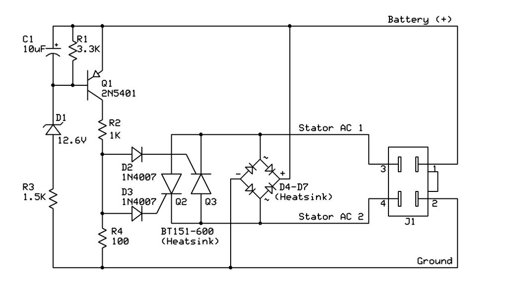
If not could you suggest a circuit that would add to the Hensim gy6 Diagram you posted in the testing a stator thread. I am going to add an ignition on warning light but it would be nice to have it as a charge warning light too.
Cheers
Dave
I have been thinking about that black wire I had spare that meters to earth. The scooter it came off had a ignition light and this could be a way of turning out the light?...just a thought.
On the subject of an ignition light, I have a new set of plastics arriving tomorrow and thought it would be usefull to have an ignition light within the circuit. Is it as simple as putting a 12amp diode between the regulator and the battery positive then connecting a bulb from the battery via the switch and then to the P terminal of the diode? Or would this not have the at rest earth to complete the circuit.
If not could you suggest a circuit that would add to the Hensim gy6 Diagram you posted in the testing a stator thread. I am going to add an ignition on warning light but it would be nice to have it as a charge warning light too.
Cheers
Dave
Trending Topics
#8
02-24-2010, 11:04 AM
Electrical Expert
Likes High Voltage In The Tub!
Likes High Voltage In The Tub!
Join Date: Dec 2008
Location: Tracy, California, USA
Posts: 3,260
Likes: 0
Received 12 Likes
on
12 Posts
I don't know about the black wire.
For the ignition light, are you thinking about an ignition light like the ones in a car (on with the ignition switch is on)? If so then all you need is a light wired from the switched battery power side of the ignition switch to ground. Or use an LED and a series resistor. You'll need to mount the light/LED in a dark recess somewhere so it can be easily seen in full sunlight.
The best way to monitor battery charge is to monitor the battery voltage. If the charging circuitry maintains 13.5 volts to 14.5 volts across the battery when the engine is running, then the charging system is working. Doing that with just a light involves some electronics to bracket those two voltage levels. It wouldn't be a lot of parts but it would have to wired up. Other methods such as monitoring the charge winding AC voltage woldn't be as good since it wouldn't be able to tell if the regulator is working right.
#9
04-22-2010, 10:34 AM

Hey LynnEdwards,
I have the exact same rectifier as shown in your picture above. My Kinroad 150 cart is also not charging, since new. I think the wires in the connector are not in its right positions. The worker at the factory must've put them in wrong.
Right now it's like this:
Red @ 1
Green @ 3
Yellow @ 2
White @ 4
I'll put the Green into "2" but the yellow (which I think has something to do with the lights), can I put it into "3"? I mean does it matter where the White and Yellow are placed in regards to "3" and "4"?
Thank you
#10
04-22-2010, 11:59 PM
Electrical Expert
Likes High Voltage In The Tub!
Likes High Voltage In The Tub!
Join Date: Dec 2008
Location: Tracy, California, USA
Posts: 3,260
Likes: 0
Received 12 Likes
on
12 Posts
Hey LynnEdwards,
I have the exact same rectifier as shown in your picture above. My Kinroad 150 cart is also not charging, since new. I think the wires in the connector are not in its right positions. The worker at the factory must've put them in wrong.
Right now it's like this:
Red @ 1
Green @ 3
Yellow @ 2
White @ 4
I'll put the Green into "2" but the yellow (which I think has something to do with the lights), can I put it into "3"? I mean does it matter where the White and Yellow are placed in regards to "3" and "4"?
Thank you
I have the exact same rectifier as shown in your picture above. My Kinroad 150 cart is also not charging, since new. I think the wires in the connector are not in its right positions. The worker at the factory must've put them in wrong.
Right now it's like this:
Red @ 1
Green @ 3
Yellow @ 2
White @ 4
I'll put the Green into "2" but the yellow (which I think has something to do with the lights), can I put it into "3"? I mean does it matter where the White and Yellow are placed in regards to "3" and "4"?
Thank you
Here's what I would do in your situation:
Unplug the regulator and start up the quad. Measure the AC voltage between the yellow and white wires at the regulator connector. I'd expect around 25 volts AC or so (or about 9.5 volts cranking if the quad isn't starting). If you get something like this voltage then I would feel free to fool around with the regulator wiring and see if it fixes the problem. Regulators are simple devices - they take AC voltage in and make regulated voltage out. If you have proper AC volts in and the battery isn't getting charged then the regulator is bad or the wiring is wrong. You have nothing to lose by experimenting with the wiring (you can't hurt the stator by overloading it - it is self limiting).
On the other hand, you may be able to damage a regulator by wiring it up wrong. So if your stator is the cause of the "no charge" problem then you want to try that first before doing something that may turn one problem into two problems.
I wish I had a better answer, but I don't.