Spark only when starter stops
#1
 10-15-2010, 03:44 PM


Join Date: Oct 2010
Posts: 9
Likes: 0
Received 0 Likes
on
0 Posts
My in-laws have a chinese ATV (Newstar) that stopped working. Actually, they have 2 that stopped working..same models.
The one that I"m working on, if I push the starter button, it cranks fine, but when testing for spark, it does not spark until I release the starter button. Then it sparks just once. Sometimes it does not spark at all, but usually, it sparks once when I release the starter button.
I took the CDI off the other machine (which is also dead) and I got no spark at all.
So my question is: Should I replace the CDI?
I read other posts here regarding CDI units...mine are both 6 pin units, but my harness clips only have 5 wires. They are 4 in one group with a 2 prong plug next to it, kind of in a "T" formation, but the 2 prong clip only has one b/w wire on it. In the picture below, it would be the bottom connection on the 2-prong clip.
Here is a picture of what mine looks like. This is actually identical to the one on mine.

I've read other places about cleaning out the stator area, but it looks like I'd have to pull the starter just to remove the stator cover on the left side and I'd rather not have to go that deep into it if possible.
Thanks for your help. My in-laws are really hoping I can repair at least one of them because they use it to maintain their ranch property.
The one that I"m working on, if I push the starter button, it cranks fine, but when testing for spark, it does not spark until I release the starter button. Then it sparks just once. Sometimes it does not spark at all, but usually, it sparks once when I release the starter button.
I took the CDI off the other machine (which is also dead) and I got no spark at all.
So my question is: Should I replace the CDI?
I read other posts here regarding CDI units...mine are both 6 pin units, but my harness clips only have 5 wires. They are 4 in one group with a 2 prong plug next to it, kind of in a "T" formation, but the 2 prong clip only has one b/w wire on it. In the picture below, it would be the bottom connection on the 2-prong clip.
Here is a picture of what mine looks like. This is actually identical to the one on mine.
I've read other places about cleaning out the stator area, but it looks like I'd have to pull the starter just to remove the stator cover on the left side and I'd rather not have to go that deep into it if possible.
Thanks for your help. My in-laws are really hoping I can repair at least one of them because they use it to maintain their ranch property.
#2
10-16-2010, 02:29 PM

Electrical Expert
Likes High Voltage In The Tub!
Likes High Voltage In The Tub!
Join Date: Dec 2008
Location: Tracy, California, USA
Posts: 3,260
Likes: 0
Received 12 Likes
on
12 Posts
Unplug the CDI and measure the resistance of the Ignition trigger pulse wire to ground. What do you measure?
Leaving the CDI unplugged crank the engine while measuring the ignition trigger pulse signal AC voltage. Set your meter to the lowest AC voltage scale you have. You should see 0.2 to 0.5 volts AC. This is a really low voltage, but it shouldn't be zero volts.
This picture is not your CDI exactly but the pinout is the same even if the connectors are different:
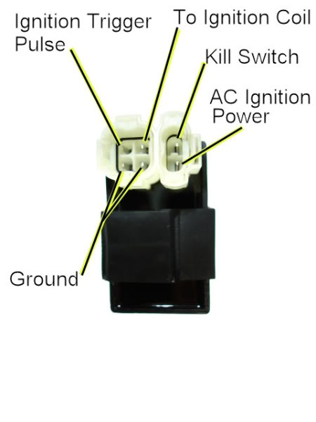
#3
10-18-2010, 12:52 PM
Join Date: Oct 2010
Posts: 9
Likes: 0
Received 0 Likes
on
0 Posts
okay, i tested resistance between the ign trig puls wire to ground wire on the plug....reading was 139.6
cranking the engine, the AC voltage from ign trig pulse signal wire to ground wire was .135v
testing for spark again today, spark was intermittent and only present at the end of the start cycle...when I released the button.
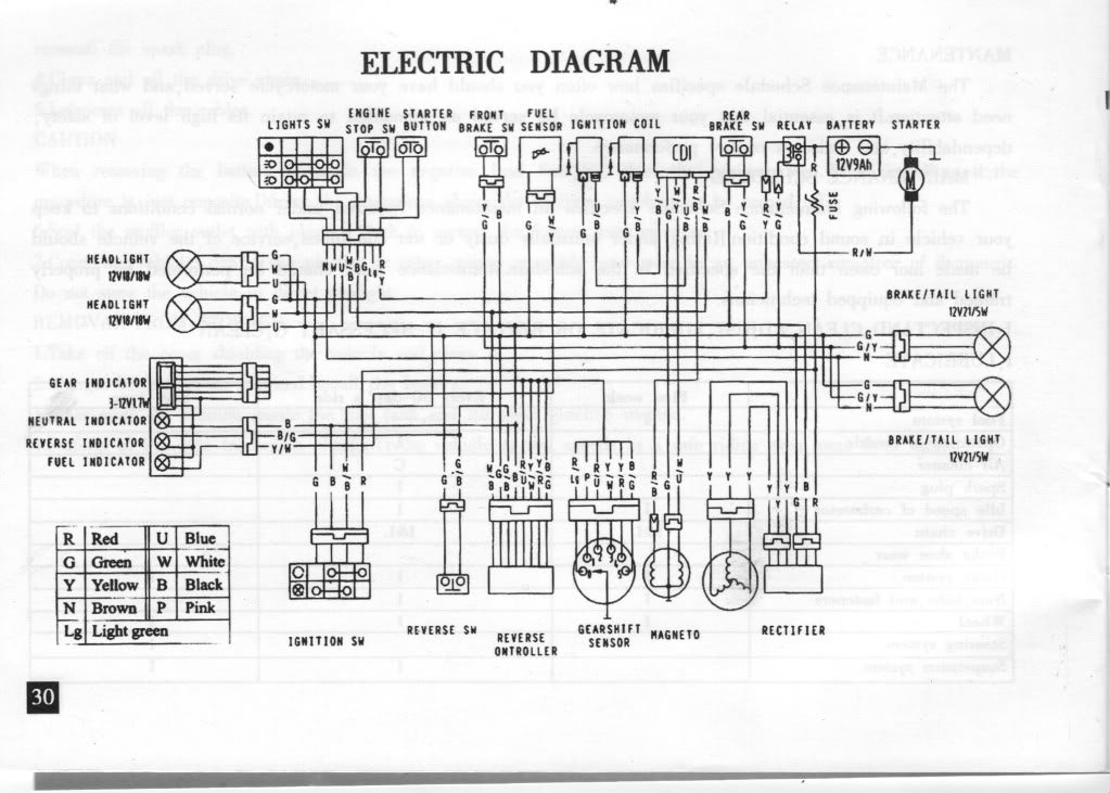
BTW...here is the wiring diagram that came with the quad. The green and b/w wire that go to the ignition switch are cut and not connected to anything. Not sure who did that, but they say it has been running like that for over a year. I toned the lines and the green wire is the AC ignition wire on the CDI..on the 2 prong clip.
cranking the engine, the AC voltage from ign trig pulse signal wire to ground wire was .135v
testing for spark again today, spark was intermittent and only present at the end of the start cycle...when I released the button.
BTW...here is the wiring diagram that came with the quad. The green and b/w wire that go to the ignition switch are cut and not connected to anything. Not sure who did that, but they say it has been running like that for over a year. I toned the lines and the green wire is the AC ignition wire on the CDI..on the 2 prong clip.
#5
10-19-2010, 12:19 AM
Electrical Expert
Likes High Voltage In The Tub!
Likes High Voltage In The Tub!
Join Date: Dec 2008
Location: Tracy, California, USA
Posts: 3,260
Likes: 0
Received 12 Likes
on
12 Posts
I need to think about this some more. There are things that don't make any sense quite yet.
Your diagram shows a two cylinder engine (two ignition coils). Is your quad a two cylinder engine? If so, you can ignore anything I've said until now, since that was based on a generic 250cc single cyclnder chinese quad. Especially ignore the CDI wiring since it does not support two ignition coils.
On your Ignition Switch: If the black white wire and the green wire follow standard generic wire colors, then these two wires are just a kill switch connection that, when shorted together with the ignition switch turned off, kills the spark. With these wires cut away the ignition switch would no longer shut off the engine - you would have to use the handlebar kill switch instead.
But the diagram shows white/black wire (not black/white) and it is wired into the lighting circuitry. Something is wrong with the diagram obviously. Hmmm.
The other conundrum is that 5 wires is not enough for a two cylinder CDI. You would need power, ground, trigger, kill, and two coil outputs. That's six pins. Like I said this makes no sense.
#6
10-19-2010, 01:01 AM
Join Date: Oct 2010
Posts: 9
Likes: 0
Received 0 Likes
on
0 Posts
LOL...wow, I never noticed that the schematic shows 2 coils...lol. I believe it IS a single 250. It has one carb and one plug and one vertical cylinder head. The coil is mounted under the front cover of the quad. Sorry for the confusion...this is the manual they got with the quad...lol.
So...ignoring the lame schematic I posted, how do my readings sound? If needed, I will go back and take pics of the engine. What I'm really trying to find out is if I need to take apart the left side of the engine to access the stator for cleaning purposes. The starter is mounted horizontally across the motor behind the cylinder. The gear drive for the starter is on the left side as well and has a small cover with three bolts. Going over the cover closely, it looks like I need to remove the starter cover to access another bolt that holds the stator cover on. I had removed all bolts from the cover and removed the bolts from the starter cap, but could not remove the cap itself. Not being familiar with this setup, I hesitate to just pry it off without checking with someone more knowledgeable.
I just can't figure out why I only get spark some times and when I do, it's only when I release the starter button. It seems to be a common problem, but I haven't been able to narrow it down to a specific cause yet. I appreciate all your time and help in this matter.
Hard to find a pic of the left side of the motor...this picture looks like the same motor, but all chromed out.
#7
10-19-2010, 09:54 PM
Electrical Expert
Likes High Voltage In The Tub!
Likes High Voltage In The Tub!
Join Date: Dec 2008
Location: Tracy, California, USA
Posts: 3,260
Likes: 0
Received 12 Likes
on
12 Posts
LOL...wow, I never noticed that the schematic shows 2 coils...lol. I believe it IS a single 250. It has one carb and one plug and one vertical cylinder head. The coil is mounted under the front cover of the quad. Sorry for the confusion...this is the manual they got with the quad...lol....
Most people with meters don't have AC voltage resolution that goes to 0.001 volts like yours. Many meters have a minimum AC voltage scale of 200 volts AC, with the least significant digit being 0.1 volts. Thus if they say they measure 0.1 volts AC it could really be 0.3 volts since they are working at the bottom of the meter resolution. But your measure 0.135 volts AC. That seems really low.
Here is what the trigger voltage on a generic chinese quad looks like if you looked at it on an oscilloscope:
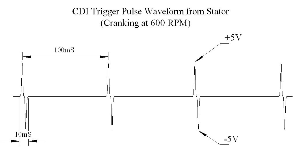
The voltage peaks are quite high, but there are long periods of nothing (0 volts) in between. Thus a averaging AC voltage measuring meter reads really low. But your meter should read higher than 0.13 volts I would think.
I don't how ambitious you are but here is a simple circuit that can be built cheaply, and will tell you if you have sufficient voltage to trigger the CDI:
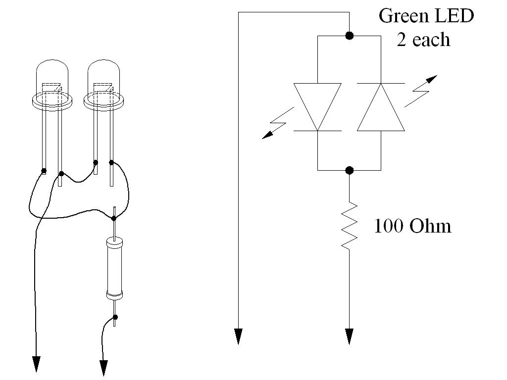
In this case the LEDs won't flash unless the trigger voltage peaks go above 2.2 volts (plus and minus). Plug this test device onto the the trigger wire and look for flashes at 10 times per second while cranking the engine.
I want to write more about this, but I have to start dinner. I'll follow up with a later post.
Trending Topics
#8
10-19-2010, 11:54 PM
Join Date: Oct 2010
Posts: 9
Likes: 0
Received 0 Likes
on
0 Posts
hmmm...I have yellow LEDs...and blue and white-with-blue tint...have to get a resistor.
As for my meter, I'm using a digital meter. I have a digital BK Precision 2408 meter. AC options are 600, 200, 2 and 200m. I had it set for 2 when I did my testing. That's why it gave me the reading it did.

If you feel that my meter may be incorrect, I can assemble the test light you suggested and test it again. Please let me know.
As for my meter, I'm using a digital meter. I have a digital BK Precision 2408 meter. AC options are 600, 200, 2 and 200m. I had it set for 2 when I did my testing. That's why it gave me the reading it did.
If you feel that my meter may be incorrect, I can assemble the test light you suggested and test it again. Please let me know.
#9
10-20-2010, 11:09 AM
Electrical Expert
Likes High Voltage In The Tub!
Likes High Voltage In The Tub!
Join Date: Dec 2008
Location: Tracy, California, USA
Posts: 3,260
Likes: 0
Received 12 Likes
on
12 Posts
Really any color LEDs are fine. LEDs are gallium-arsenide semiconductors which don't conduct in the forward direction (or light up) until you get about 2 volts across them. It varies a bit with color. Red LEDs are about 1.8 volts, while green is about 2.2 volts. Blue is even higher, with yellow in between the red and green. The idea behind using LEDs and that if they light up you know your trigger voltage is reaching at least 2 volts peak - which should be enough to trigger the CDI. You cannot really tell this for certain with a meter.
One LED measures the positive pulse while the other measures the negative pulse. The positive pulse arms the CDI inside, the negative pulse fires the CDI.
The fact that you get a spark at all sort of suggests that the CDI, AC power to the CDI, spark plug, and coil is capable of generating spark. The only thing that happens when you turn off the starter motor is that the switching off of a very large current generates transient high frequency voltage spikes. The trigger inpur to the CDI would be susceptible to these spikes.
Others have reported this problem. Some have never come back with the final solution, but some have. The problem in two cases was with the trigger pickup coil outside the flywheel. In one case cleaning out rust from the stator fixed it, while the other found magnetic debris stuck to the pickup coil.
The trigger pickup coil has a magnet inside the coil. Rather than spinning magnets past the pickup coil, the flywheel has a raised steel bump that does a close flyby past the pickup coil. It is the leading and trailing edges of this raised steel bump that bend the magnetic field from the pickup coil magnet and induces the plus and minus pulses in the coil.
The trigger coil is designed such that it has a very small detection range. The magnet inside is all bottled up in a steel housing with a small opening near the flywheel. The reason for keeping the magnetic field bottled up is to keep the trigger coil from seeing interference from the large powerful spinning magnets inside the flywheel that power the CDI and keep the battery charged.
If there is magnetic debris in the stator housing it can get attracted and lodged in the pickup coil end. This further bottles up the trigger pickup field and reduces its detection range to the point that the CDI won't trigger. The gap between the trigger coil and the raised bump is also important. On some quads this is adjustable. (Eton quads specify this gap at 0.025" to use as a comparison data point.)
It could also be a bad CDI. The LED/resistor test fixture will allow you see if you have a good trigger signal. If you do then I would try the CDI next. If you don't then looking into the stator is next.
#10
10-20-2010, 10:35 PM
Join Date: Oct 2010
Posts: 9
Likes: 0
Received 0 Likes
on
0 Posts