bear tracker clone bad stator/cdi both?
#1
 07-25-2012, 11:48 PM


Join Date: May 2012
Posts: 19
Likes: 0
Received 0 Likes
on
0 Posts
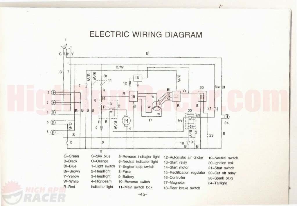
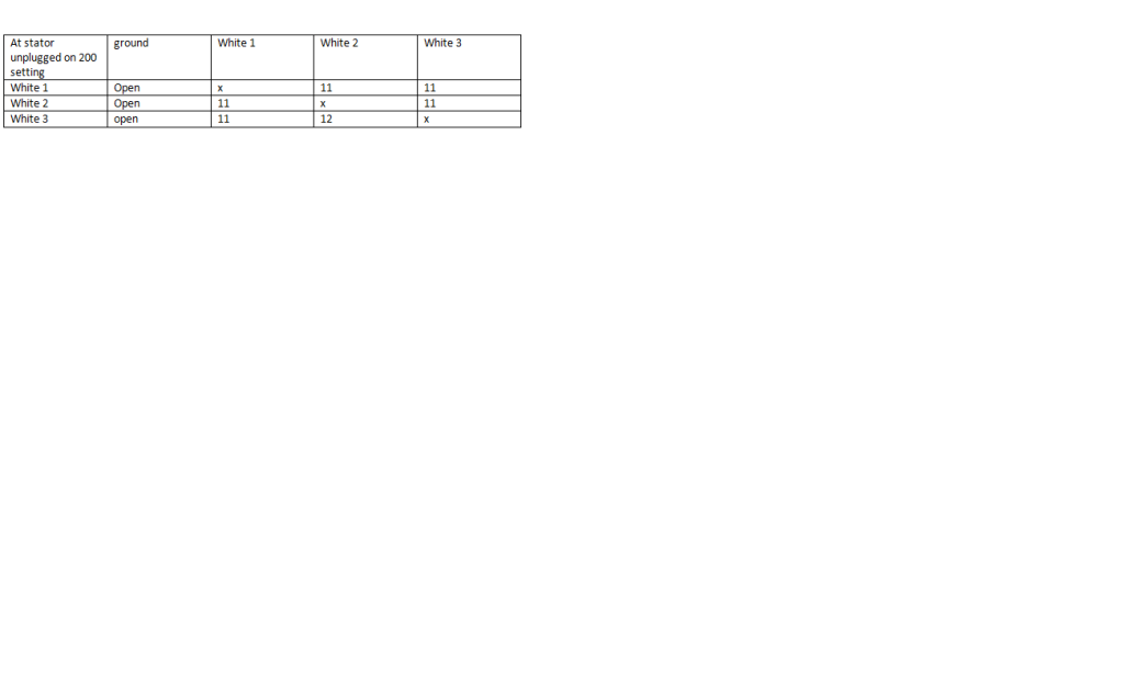
I have picked up a 99 bear tracker clone pretty much for free and looks brand new. I believe it to be a jianshe or baja wilderness with the js250 2006 motor. There is no data plate. The people before me did a hack job on the wiring which I ended up tearing out every wire because it was so screwed up. I have started with the basics of just trying to get spark. I purchased new handlebar switch assembly ngk plug, new coil, they had purchased a new cdi, but it was hooked up wrong. I hope they did not fry it. I cleaned the stator up. They had obviously taken it off and smashed the red wire from the source coil while putting it back on and it was shorting to the stator tray that hold the stator to the case. I “fixed’ it by cleaning it up and shrink wrap. I purchased new carb as well. I have I hope fixed the wiring the situation to the cdi. They had the ign. Coil charge wire from cdi going to ground and the ign. Coil wire hooked up to the kill wire. I have adjusted valves out to spec. about once every 10 seconds while cold it will pop and run for about 3 strokes then died and burp out the carb. Not a backfire though. It will also sometimes back wind on itself for a split second when it dies. I have attached my readings in the tables below. They are all over the board. Something with it seems screwy. Figure I would run it past all you gurus before I dumped 250 on a cdi and stator. Can't really find a whole lot on 7 wire cdi. Ends had been cut off of it and the original. I also attached a wiring diagram as to how I wired it up. I did away with the shut off relay and all kill switches have been unhooked at cdi (I have a safety backup to kill it if need be) I am getting a fairly consistent spark but it is extremely weak. I can barely see it. In the tables you can see I did redundant tests on wires to proof my readings. I also pulled the timing chain cover (Overhead cam engine) and it is in good shape at TDC, the timing mark on cam gear is about � tooth off from mark on casing.
With only ground (black #1) hooked up to cdi, the blue and green wires are positive to continuity to ground. The ignition coil wire is also positive for continuity to ground
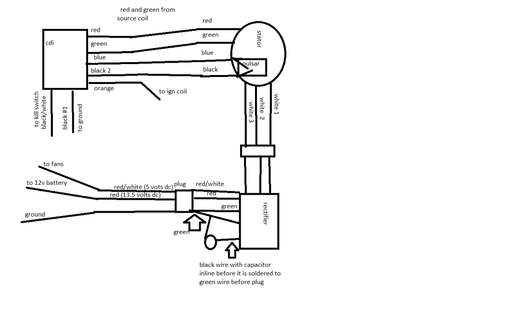
Thoughts? am I missing something simple And ether has no effect on whether it will start or not . First image is one I did. Second wiring diagram is one i followed with a grain of salt and the parts had the smae amount of wires, just not the right color. Sorry for the long post but wanted to give all info I could give you.


With only ground (black #1) hooked up to cdi, the blue and green wires are positive to continuity to ground. The ignition coil wire is also positive for continuity to ground
Thoughts? am I missing something simple And ether has no effect on whether it will start or not . First image is one I did. Second wiring diagram is one i followed with a grain of salt and the parts had the smae amount of wires, just not the right color. Sorry for the long post but wanted to give all info I could give you.
#2
07-26-2012, 11:12 PM
Join Date: May 2012
Posts: 19
Likes: 0
Received 0 Likes
on
0 Posts
#3
07-29-2012, 11:02 PM

Electrical Expert
Likes High Voltage In The Tub!
Likes High Voltage In The Tub!
Join Date: Dec 2008
Location: Tracy, California, USA
Posts: 3,260
Likes: 0
Received 12 Likes
on
12 Posts
I've been on vacation - actually I'm still on vacation - so I've been out of touch. I may still be out of touch until thursday when I get back.
Measuring weak spark is so subjective. How sure are you that the spark is weak? If you double the gap on a spare plug does it still spark? Maybe this "weak spark" thing is a red herring...
In any case I would unplug the CDI and
1) measure the AC voltage between the source coil pins at the CDI connector (red and green wires) while cranking the engine.
2) Then measure the voltage between the trigger pins while cranking the engine. Use the lowest AC scale you have.
What do you measure for these two tests?
I'm having a little trouble understanding this statement:
So when you hook one single gound wire from ground to to an otherwise disconnected CDI, suddenly two other wires (green and blue) on the stator now show resistance to ground where they didn't before? This is not possible....
Measuring weak spark is so subjective. How sure are you that the spark is weak? If you double the gap on a spare plug does it still spark? Maybe this "weak spark" thing is a red herring...
In any case I would unplug the CDI and
1) measure the AC voltage between the source coil pins at the CDI connector (red and green wires) while cranking the engine.
2) Then measure the voltage between the trigger pins while cranking the engine. Use the lowest AC scale you have.
What do you measure for these two tests?
I'm having a little trouble understanding this statement:
With only ground (black #1) hooked up to cdi, the blue and green wires are positive to continuity to ground.
So when you hook one single gound wire from ground to to an otherwise disconnected CDI, suddenly two other wires (green and blue) on the stator now show resistance to ground where they didn't before? This is not possible....
Last edited by LynnEdwards; 07-29-2012 at 11:04 PM. Reason: clarification
#4
07-31-2012, 10:14 PM
Join Date: May 2012
Posts: 19
Likes: 0
Received 0 Likes
on
0 Posts
I've been on vacation - actually I'm still on vacation - so I've been out of touch. I may still be out of touch until thursday when I get back.
Measuring weak spark is so subjective. How sure are you that the spark is weak? If you double the gap on a spare plug does it still spark? Maybe this "weak spark" thing is a red herring...
In any case I would unplug the CDI and
1) measure the AC voltage between the source coil pins at the CDI connector (red and green wires) while cranking the engine.
2) Then measure the voltage between the trigger pins while cranking the engine. Use the lowest AC scale you have.
What do you measure for these two tests?
I'm having a little trouble understanding this statement:
So when you hook one single gound wire from ground to to an otherwise disconnected CDI, suddenly two other wires (green and blue) on the stator now show resistance to ground where they didn't before? This is not possible....
Measuring weak spark is so subjective. How sure are you that the spark is weak? If you double the gap on a spare plug does it still spark? Maybe this "weak spark" thing is a red herring...
In any case I would unplug the CDI and
1) measure the AC voltage between the source coil pins at the CDI connector (red and green wires) while cranking the engine.
2) Then measure the voltage between the trigger pins while cranking the engine. Use the lowest AC scale you have.
What do you measure for these two tests?
I'm having a little trouble understanding this statement:
So when you hook one single gound wire from ground to to an otherwise disconnected CDI, suddenly two other wires (green and blue) on the stator now show resistance to ground where they didn't before? This is not possible....
first, I consider it weak spark because I have messed with countless spark plugs and have never seen anything this small be able to spark an engine over. you can't hear a snap or see it if the lights are on. It must be able to because it will randomly fire. So I am probably wrong which i am used to.
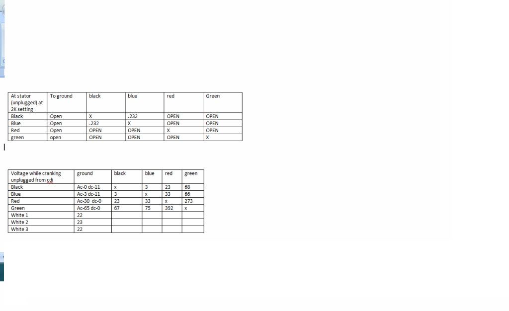
voltage between the source coil wires are 33.7 on 200 scale on a just purchased multimeter and 337 on my old multimeter. I am not sure which to believe.
voltage between the blue and black trigger wires is 1.0 volts on both the old and new multimeters
I need to go buy a better one i think the one i just purchased was a $20 one from autozone lowest setting is 200 ac old one goes down to 2.
Sorry, I did not mean to confuse on the last statement in the original post. with the cdi unhooked from the stator, I hook up the frame ground wire to the cdi as the only one hooked up. the green and blue wires at the cdi show continuity to ground. not the wires to the stator since it is not hooked up at all. Should the green and blue wires be grounded out inside the cdi? green goes to source coil and blue to trigger pulsar coil.
#5
08-01-2012, 09:49 PM
Electrical Expert
Likes High Voltage In The Tub!
Likes High Voltage In The Tub!
Join Date: Dec 2008
Location: Tracy, California, USA
Posts: 3,260
Likes: 0
Received 12 Likes
on
12 Posts
My comments embedded in blue:
No problem, I appreciate your help on this as I am sure you are a quite busy person.
first, I consider it weak spark because I have messed with countless spark plugs and have never seen anything this small be able to spark an engine over. you can't hear a snap or see it if the lights are on. It must be able to because it will randomly fire. So I am probably wrong which i am used to. [Or I could be wrong too. Does it jump the plug gap if you double it? That would be a clue...]
voltage between the source coil wires are 33.7 on 200 scale on a just purchased multimeter and 337 on my old multimeter. I am not sure which to believe. [I was looking at your charts in the earlier post more closely tonight. 337 volts is unbelievably high. 33.7 is on the low side but believable. Perhaps your other meter just has a burnt out decimal point in the display. ]
voltage between the blue and black trigger wires is 1.0 volts on both the old and new multimeters [This seems high to me, but if the CDI is triggering regularly (and producing spark) at ten times per second while cranking the starter then it is working.]
I need to go buy a better one i think the one i just purchased was a $20 one from autozone lowest setting is 200 ac old one goes down to 2.
[If you can verify that the only thing wrong with your older meter is that a decimal point is missing on some scales, then perhaps you can use both meters - one to get the higher resolution (2 volts AC full scale), and the other to figure out where the decimal point goes...]
Sorry, I did not mean to confuse on the last statement in the original post. with the cdi unhooked from the stator, I hook up the frame ground wire to the cdi as the only one hooked up. the green and blue wires at the cdi show continuity to ground. not the wires to the stator since it is not hooked up at all. Should the green and blue wires be grounded out inside the cdi? green goes to source coil and blue to trigger pulsar coil. [On most stators one side of the trigger and AC ignition power windings are grounded locally at the stator. An additional (and redundant) ground wire then goes to the CDI. In your case (based your observtions, and on the wiring diagram you posted earlier, It looks like all the grounding happens at the CDI. From a noise immunity standpoint (i.e. unwanted voltage pickup from adjacent wires) having all the grounding happen right at (and inside) the CDI makes a lot of sense. ]
#6
08-01-2012, 10:11 PM
Electrical Expert
Likes High Voltage In The Tub!
Likes High Voltage In The Tub!
Join Date: Dec 2008
Location: Tracy, California, USA
Posts: 3,260
Likes: 0
Received 12 Likes
on
12 Posts
AS I mentioned in my last post I looked at the data in this post more carefully.
Try as I might, I cannot embed comments in your post below. Nor can I delete out the irrelevant stuff without without the whole thing disappearing. So I'll have to put all my comments here up above your post...
In your ohms table you listed red and green wires as being open - looking into the stator on the 2K ohm scale. Yet this should not be. An open AC ignition charge coil would not produce 30+ volts AC at cranking speeds, nor would it produce spark. There is a conflict here. What happens if you go to the 5K or 10K ohms scale. Do you measure any resistance now?
You also get DC voltage from the black, and blue wires to ground. This does not make sense to me. COuld you verify that again please? There should be be no source for any DC voltage with the CDI disconnected.
I have picked up a 99 bear tracker clone pretty much for free and looks brand new. I believe it to be a jianshe or baja wilderness with the js250 2006 motor. There is no data plate. The people before me did a hack job on the wiring which I ended up tearing out every wire because it was so screwed up. I have started with the basics of just trying to get spark. I purchased new handlebar switch assembly ngk plug, new coil, they had purchased a new cdi, but it was hooked up wrong. I hope they did not fry it. I cleaned the stator up. They had obviously taken it off and smashed the red wire from the source coil while putting it back on and it was shorting to the stator tray that hold the stator to the case. I �fixed� it by cleaning it up and shrink wrap. I purchased new carb as well. I have I hope fixed the wiring the situation to the cdi. They had the ign. Coil charge wire from cdi going to ground and the ign. Coil wire hooked up to the kill wire. I have adjusted valves out to spec. about once every 10 seconds while cold it will pop and run for about 3 strokes then died and burp out the carb. Not a backfire though. It will also sometimes back wind on itself for a split second when it dies. I have attached my readings in the tables below. They are all over the board. Something with it seems screwy. Figure I would run it past all you gurus before I dumped 250 on a cdi and stator. Can't really find a whole lot on 7 wire cdi. Ends had been cut off of it and the original. I also attached a wiring diagram as to how I wired it up. I did away with the shut off relay and all kill switches have been unhooked at cdi (I have a safety backup to kill it if need be) I am getting a fairly consistent spark but it is extremely weak. I can barely see it. In the tables you can see I did redundant tests on wires to proof my readings. I also pulled the timing chain cover (Overhead cam engine) and it is in good shape at TDC, the timing mark on cam gear is about � tooth off from mark on casing.
With only ground (black #1) hooked up to cdi, the blue and green wires are positive to continuity to ground. The ignition coil wire is also positive for continuity to ground
Thoughts? am I missing something simple And ether has no effect on whether it will start or not . First image is one I did. Second wiring diagram is one i followed with a grain of salt and the parts had the smae amount of wires, just not the right color. Sorry for the long post but wanted to give all info I could give you.
#7
08-02-2012, 02:25 PM
Join Date: May 2012
Posts: 19
Likes: 0
Received 0 Likes
on
0 Posts
Took readings with my new multimeter. the dc volts on on the blue and black are not there. They both show zero to ground
For the green and red wires.The ohms on my multimeter show a 1 on any setting below the 20K on the 20k setting, it shows 11.48 However, when i first touched the wire they showed a 1 on all settings then i bumped the starter real quick,stopped and tested and it started out at a reading of 11.17 and climbed slowly to 11.48 on 20k setting while no cranking. it still shows 32-33 volts. let me know what address you keep your tip jar at. because you sure are earning it
i still need to pull plug and double gap and see what it does. I will do that tonight after dark so it is easier to see.
For the green and red wires.The ohms on my multimeter show a 1 on any setting below the 20K on the 20k setting, it shows 11.48 However, when i first touched the wire they showed a 1 on all settings then i bumped the starter real quick,stopped and tested and it started out at a reading of 11.17 and climbed slowly to 11.48 on 20k setting while no cranking. it still shows 32-33 volts. let me know what address you keep your tip jar at.
because you sure are earning iti still need to pull plug and double gap and see what it does. I will do that tonight after dark so it is easier to see.
Trending Topics
#8
08-02-2012, 11:32 PM
Electrical Expert
Likes High Voltage In The Tub!
Likes High Voltage In The Tub!
Join Date: Dec 2008
Location: Tracy, California, USA
Posts: 3,260
Likes: 0
Received 12 Likes
on
12 Posts

.....For the green and red wires.The ohms on my multimeter show a 1 on any setting below the 20K on the 20k setting, it shows 11.48 However, when i first touched the wire they showed a 1 on all settings then i bumped the starter real quick,stopped and tested and it started out at a reading of 11.17 and climbed slowly to 11.48 on 20k setting while no cranking. it still shows 32-33 volts..
This is really bizarre, and completely wrong. This maybe part (or all) of the problem. 11.48K ohms is too high a resistance to feed enough power to drive the CDI. And the resistance should not change after bumping the starter motor. Please repeat these measurements, and if they hold up then there is something very wrong in your stator AC Ignition Power winding. That kind of source impedance would cause very weak spark...
Perhaps it's time to pull off the stator and look fro corroded joints and/or
burn't areas...
#9
08-11-2012, 02:15 AM
Join Date: May 2012
Posts: 19
Likes: 0
Received 0 Likes
on
0 Posts
ok, had a good day health wise so I pulled the stator again and looked for anything unusual. nothing but the smashed wire i fixed by cutting and soldering, shrink wrap. However, with the weird readings I am getting, I just went ahead and purchased the new stator. the new handlebar switch($24) I put on, coil($12) and stator($119), original purchase price (about $50) I am into this for about $200 now. Hopefully,this does it. If not a cdi is 44.95. It will be a cheap ride for my 8 year old. let him graduate up from his 110cc tao tao. Can't really afford name brand being on disability, but he will be tickled pink to get this. then he can give his tao tao to my 4 year old.