No spark: Odd CDI system
#1
 03-10-2014, 04:46 AM


Join Date: Mar 2014
Posts: 6
Likes: 0
Received 0 Likes
on
0 Posts
Hi Forum, I have a Chinese 300cc 4x4 quad bike that has no spark. The quad is sold here in Australia under the brand 'Atomik' but it is also known elsewhere, as a BuYang FA-H300.
Firstly, the majority of the electrics are working. The starter motor cranks, the lights, indicators, instruments, horn etc. all work fine. The battery is less than a year old and holds charge ok. It seems like the problem is limited to no spark.
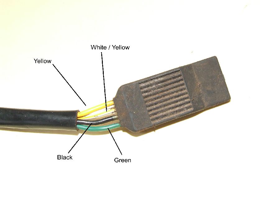
The quad's ignition system seems to be a bit non-standard and I haven't had had any success getting information or a wiring diagram for it. The main difference from typical CDI systems is that the stator doesn't have the typical 'exciter' + 'trigger' coils. It has two wires from the stator to the CDI unit, but both wires are connected to a single coil that has a resistance of 200Ω and both wires show open circuit to negative/earth. The other anomaly, that I haven't come across before, is the ignition coil has two wires connected to it, apart from the plug lead. One wire is Red/White and is connected to a 6.8mm spade terminal on the coil and has +12V when the ignition switch is on. The other wire is Black/Yellow and connects to a smaller 4.8mm spade terminal. This Black/Yellow wire runs back to the CDI unit.
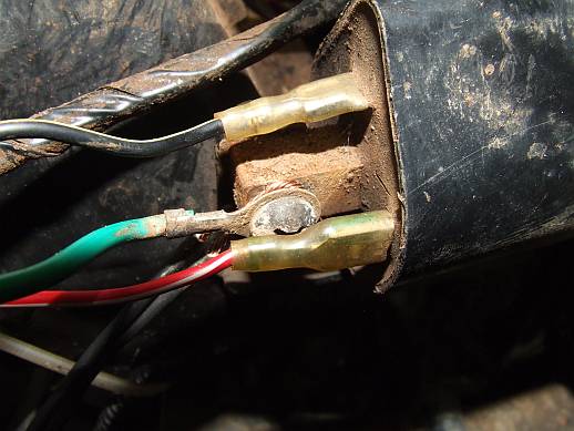
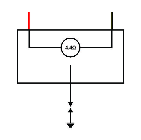
Resistance readings of the coil are a bit confounding. The two low-voltage wires and the spark-plug wire, are all open circuit to negative/earth. Resistance between the Red/White and Black/Yellow wires is 4.4Ω

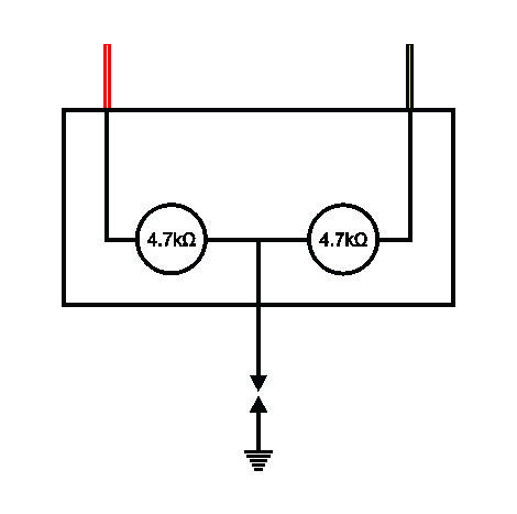
Resistance between the spark-plug wire and the Red/White is the same as the resistance between the spark-plug wire and the Black/Yellow wire. 4.7kΩ

I don't really understand how I can get these readings unless there is electronics in the coil.
If anyone can shed some light on this ignition system, I would be extremely grateful.
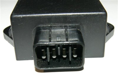
This is the style of CDI unit I have.
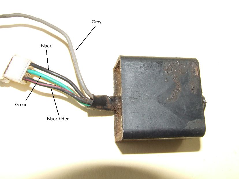
There are also a couple of components I am unable to identify. Does anyone have any idea what these are?
Sorry my second only post is a massive "gimmee", but I have been trying to sort this out myself and I'm stumped. I'm hoping you knowledgeable people on this great forum can steer me in the right direction.
Firstly, the majority of the electrics are working. The starter motor cranks, the lights, indicators, instruments, horn etc. all work fine. The battery is less than a year old and holds charge ok. It seems like the problem is limited to no spark.
The quad's ignition system seems to be a bit non-standard and I haven't had had any success getting information or a wiring diagram for it. The main difference from typical CDI systems is that the stator doesn't have the typical 'exciter' + 'trigger' coils. It has two wires from the stator to the CDI unit, but both wires are connected to a single coil that has a resistance of 200Ω and both wires show open circuit to negative/earth. The other anomaly, that I haven't come across before, is the ignition coil has two wires connected to it, apart from the plug lead. One wire is Red/White and is connected to a 6.8mm spade terminal on the coil and has +12V when the ignition switch is on. The other wire is Black/Yellow and connects to a smaller 4.8mm spade terminal. This Black/Yellow wire runs back to the CDI unit.
Resistance readings of the coil are a bit confounding. The two low-voltage wires and the spark-plug wire, are all open circuit to negative/earth. Resistance between the Red/White and Black/Yellow wires is 4.4Ω
Resistance between the spark-plug wire and the Red/White is the same as the resistance between the spark-plug wire and the Black/Yellow wire. 4.7kΩ
I don't really understand how I can get these readings unless there is electronics in the coil.
If anyone can shed some light on this ignition system, I would be extremely grateful.
This is the style of CDI unit I have.
There are also a couple of components I am unable to identify. Does anyone have any idea what these are?
Sorry my second only post is a massive "gimmee", but I have been trying to sort this out myself and I'm stumped. I'm hoping you knowledgeable people on this great forum can steer me in the right direction.
#2
03-10-2014, 06:12 AM

#3
03-10-2014, 08:50 PM
Join Date: Mar 2014
Posts: 6
Likes: 0
Received 0 Likes
on
0 Posts
It looks like I have a DC ignition, based on a TPI (Transistor Pointless Ignition) system.
The 8-pin TPI ignitor unit seems to be common in older Yamaha and Honda motorbikes.
As I haven't been able to troubleshoot properly, I'll probably just start replacing components blind. The easiest component to source is the ignitor. The 2-wire coil has been a bit harder to find.
#4
03-10-2014, 09:13 PM
Join Date: Mar 2014
Posts: 6
Likes: 0
Received 0 Likes
on
0 Posts
#5
03-10-2014, 09:15 PM

#6
03-12-2014, 08:20 PM
Join Date: Mar 2014
Posts: 6
Likes: 0
Received 0 Likes
on
0 Posts
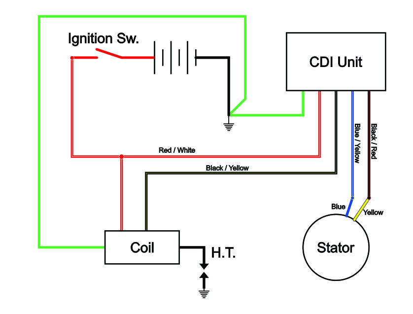
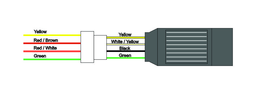
Well I finally found a wiring diagram for my quad's clone (BuYang 300 4x4) and it looks pretty close.
So it seems like I have a DC CDI system, and I may have a faulty ignitor.
The readings on the coil make a bit more sense now. I realise the circuit from the spark-plug wire to the black/Yellow wire has both the primary and secondary windings in series, but the meter is only 'reading' the high resistance of the secondary winding. So both readings from the two wires look to have the same high resistance of the secondary winding.
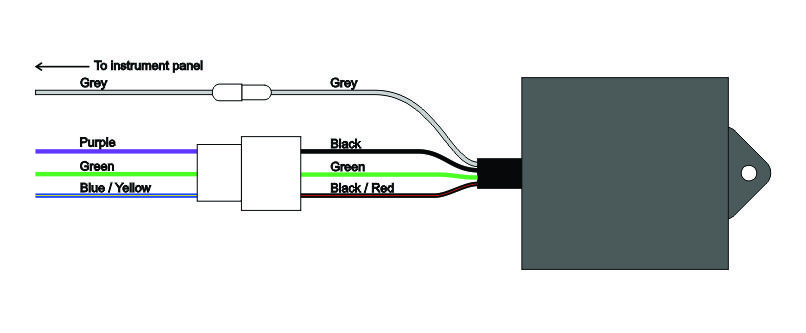
My two mystery components appear to be the speed limiter and the "Freezer Proof Unit" (a tad superfluous here in tropical Australia)
Is there anybody that can tell me the relationship between the gear-shift Up/Down switches and the speed-limiter?
Also, does anyone know the principle behind this type of DC CDI system? Does the Ignitor unit simply pulse the negative to the ignition coil, similar to points? Or does the Ignitor raise the pulse voltage above 12V, across the primary winding of the coil?
BuYang 300cc 4x4 Wiring Diagram
So it seems like I have a DC CDI system, and I may have a faulty ignitor.
The readings on the coil make a bit more sense now. I realise the circuit from the spark-plug wire to the black/Yellow wire has both the primary and secondary windings in series, but the meter is only 'reading' the high resistance of the secondary winding. So both readings from the two wires look to have the same high resistance of the secondary winding.
My two mystery components appear to be the speed limiter and the "Freezer Proof Unit" (a tad superfluous here in tropical Australia)
Is there anybody that can tell me the relationship between the gear-shift Up/Down switches and the speed-limiter?
Also, does anyone know the principle behind this type of DC CDI system? Does the Ignitor unit simply pulse the negative to the ignition coil, similar to points? Or does the Ignitor raise the pulse voltage above 12V, across the primary winding of the coil?
BuYang 300cc 4x4 Wiring Diagram

Thread
Thread Starter
Forum
Replies
Last Post
speedbuff
Polaris Ask an Expert! In fond memory of Old Polaris Tech.
13
11-11-2020 10:16 AM
jrooker6
Polaris
18
04-23-2016 07:36 PM
ATVC Correspondent
Performance Mods and Project Quads
5
10-10-2015 10:20 AM
TheATVSuperStore.com
TheATVSuperStore
0
09-09-2015 07:43 PM
Currently Active Users Viewing This Thread: 3 (0 members and 3 guests)