110cc Kazuma Falcon Rectifier
#1
 09-27-2009, 09:21 PM


Join Date: Sep 2009
Posts: 7
Likes: 0
Received 0 Likes
on
0 Posts

#2
09-28-2009, 07:37 AM
Join Date: Sep 2009
Posts: 7
Likes: 0
Received 0 Likes
on
0 Posts
#3
09-28-2009, 08:17 AM
Join Date: Sep 2009
Posts: 7
Likes: 0
Received 0 Likes
on
0 Posts
#4
09-28-2009, 09:58 AM
Join Date: Sep 2009
Posts: 7
Likes: 0
Received 0 Likes
on
0 Posts
#5
09-28-2009, 10:27 AM

Electrical Expert
Likes High Voltage In The Tub!
Likes High Voltage In The Tub!
Join Date: Dec 2008
Location: Tracy, California, USA
Posts: 3,260
Likes: 0
Received 12 Likes
on
12 Posts
There are a lot about four pin rectifier/regulators that I don't understand. I've taken apart three of them, and they are all different inside. Even worse, they are wired up differently externally, and not compatible with each other. All three use the same four pin connector as shown in your picture.
Of the three this one most closely resembles yours in that it is advertised as being a replacement for 110cc machines only. The other two were advertized as being compatible with 150cc/110cc machines.
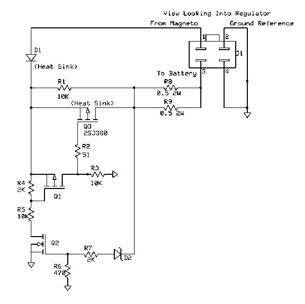
The connector is shown looking into the regulator as in your picture. Note it's wired differently than the picture you put up. And to make it even more confusing, this regulator cannot work with almost all the wiring diagrams for 110cc machines I've seen. So either the wiring diagrams are all wrong, or there is yet a fourth version of 110cc regulators. I don't have a 110cc machine to play with so I don't have any way to resolve these discrepancies.
On your new regulator are pins 2 and 4 shorted together?
If you start up the bike (you can do this with the regulator disconnected), what is the AC voltage between the White and Yellow wires at idle. Then what is the ACvoltage from both White and Yellow to engine ground?
Of the three this one most closely resembles yours in that it is advertised as being a replacement for 110cc machines only. The other two were advertized as being compatible with 150cc/110cc machines.
The connector is shown looking into the regulator as in your picture. Note it's wired differently than the picture you put up. And to make it even more confusing, this regulator cannot work with almost all the wiring diagrams for 110cc machines I've seen. So either the wiring diagrams are all wrong, or there is yet a fourth version of 110cc regulators. I don't have a 110cc machine to play with so I don't have any way to resolve these discrepancies.
On your new regulator are pins 2 and 4 shorted together?
If you start up the bike (you can do this with the regulator disconnected), what is the AC voltage between the White and Yellow wires at idle. Then what is the ACvoltage from both White and Yellow to engine ground?
#6
09-28-2009, 01:20 PM
Join Date: Sep 2009
Posts: 7
Likes: 0
Received 0 Likes
on
0 Posts
Ok, we decided to bypass the rectifier for now.
Now, no spark. I took a look at your previous posts. We are only getting 40 volts AC coming from the engine Ignition Power. The other pulsing one seems fine. Is that enough to power the CDI?
did the ohms test. 120 for the trigger and nothing on the ignition power.
Getting 25 volts from the CDI to the coil. Is that normal? When we hook up the wire to the coil and turn it over, we get no voltage. Maybe a bad coil?
Thanks again for all your help.
#7
09-28-2009, 11:15 PM
Electrical Expert
Likes High Voltage In The Tub!
Likes High Voltage In The Tub!
Join Date: Dec 2008
Location: Tracy, California, USA
Posts: 3,260
Likes: 0
Received 12 Likes
on
12 Posts
When you said you "got nothing" for the resistance of the ignition power winding, what exactly do you mean? "Nothing" can mean zero ohms or infinite ohms. It cold also mean you had your meter on a really low scale and then didn't see that it was actually around 400 ohms.
Was the voltage that you measured (25 volts) from the CDI to the coil done with the CDI disconnected? And then you got 0 volts when connected? Was the voltage you measured at the coil AC or DC? Normally I would say that the voltage measured at the CDI/Ignition coil interface is meaningless since it depends a lot on the CDI design (there is more than one) and the meter design (different meters read differently). The waveforms here are high voltage very narrow pulses - not something that is normally measured with a meter. I'm asking the questions only to get as much info as possible. Maybe it won't help, and maybe with other info it will be a clue.
40 volts AC is really low compared to what I've measured before. Is your starter cranking slow? The voltage output is directly proportional to cranking speed. Here's another test to try: Measure the AC ignition power winding again (CDI unplugged) only this time set your meter to read AC current on the 200 mA (or so) scale. To measure current you have to change your red lead over to the "mA" jack which is different from the one used to measure voltage. Black lead goes to engine ground as usual. When you crank the starter, how much current do you read? It should be in the 150 mA range. 150 mA is the same as 150 milliamps, or 0.150 amps. Just be sure you are measuring AC current and not DC curent.
Trending Topics
#8
10-03-2009, 01:15 PM
Join Date: Sep 2009
Posts: 7
Likes: 0
Received 0 Likes
on
0 Posts

#9
05-24-2010, 01:13 PM
