linhai 300 atv
#21
 03-01-2012, 11:31 AM


Join Date: Feb 2012
Posts: 14
Likes: 0
Received 0 Likes
on
0 Posts
Also them blue wire and yellow wire go to a plug then change colors which I followed and they both go to cdi blue wire from pikup coil turns into blue/white and goes to cdi and yellow wire turns into black/red and also goes to cdi I measured resistance in both and come up with 3.4 on both wires. checking at cdi all 5 wires comes out at bk/red 0.13, blue/white 0.13, pink 0.00,green0.00,yellow/black0.00. other test key on for volt is yellow/black 11.24 and also pink 11.24 Thanks,Tim
#22
03-02-2012, 01:16 AM

Electrical Expert
Likes High Voltage In The Tub!
Likes High Voltage In The Tub!
Join Date: Dec 2008
Location: Tracy, California, USA
Posts: 3,260
Likes: 0
Received 12 Likes
on
12 Posts
Whenever quoting wire colors be sure to quote only the wire colors on the wiring harness side of any connector. The short pigtail wire colors are not relevant at all. Here is the reason: I don't have a wiring diagram, and am trying to piece one together based on the info you give me. A red/black wire entering the taped up harness will still be red/black when it comes out, almost certainly any red/black wire that emerges elsewhere is the same wire. I'm relying on that fact to piece together a wiring diagram.
I'm assuming the blk/red wire in the harness is the blk/pink wire you reported earlier at the CDI. .
.
I'm not following you when you say you measured 3.4 something on both wires. 3.4 what? From what wire to what wire? Neither of these sounds right...
Here is a 300cc Buyang atv wiring diagram with a CDI that matches your colors sort of. It has a Blk/yel wire at the CDI instead of Yel/blk. And it has a Blu/yel instead of a blu/wht. Lets try it and see if it pans out... Click on the thumbnail to enlarge...
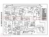
Unplug the CDI and measure the resistance between the Blu/wht wire and the black red wire. Use the 500 ohm scale. What do you measure (report both the value and the scale you used)? Also, each of these wires when measured in turn to ground should measure infinite resistance (open, or "OL" on some meters indicating open loop").
Also remeasure the Yel/Blk wire resistance to engine ground (ignition off). What do you measure (report both the value and the scale you used)? Use the lowest ohms scale you have (like 2 ohms or 20 ohms). Don't use any scale that has a "K" in it or an "M" in it. 2K ohms is 2000 ohms. That is too high. 2M ohms is two million ohms and that is way, way, way too high. The value should be low (less than 1 ohm - like 0.7 ohms or something like that), but it should not be zero ohms
Your Yel/Blk and Pink wire voltage measurements match exactly the expected results for the above diagram (except your battery isn't fully charged - but that's another issue for later...)
I'm assuming the blk/red wire in the harness is the blk/pink wire you reported earlier at the CDI.
.I'm not following you when you say you measured 3.4 something on both wires. 3.4 what? From what wire to what wire? Neither of these sounds right...
Here is a 300cc Buyang atv wiring diagram with a CDI that matches your colors sort of. It has a Blk/yel wire at the CDI instead of Yel/blk. And it has a Blu/yel instead of a blu/wht. Lets try it and see if it pans out...
Click on the thumbnail to enlarge...
Unplug the CDI and measure the resistance between the Blu/wht wire and the black red wire. Use the 500 ohm scale. What do you measure (report both the value and the scale you used)? Also, each of these wires when measured in turn to ground should measure infinite resistance (open, or "OL" on some meters indicating open loop").
Also remeasure the Yel/Blk wire resistance to engine ground (ignition off). What do you measure (report both the value and the scale you used)? Use the lowest ohms scale you have (like 2 ohms or 20 ohms). Don't use any scale that has a "K" in it or an "M" in it. 2K ohms is 2000 ohms. That is too high. 2M ohms is two million ohms and that is way, way, way too high. The value should be low (less than 1 ohm - like 0.7 ohms or something like that), but it should not be zero ohms
Your Yel/Blk and Pink wire voltage measurements match exactly the expected results for the above diagram (except your battery isn't fully charged - but that's another issue for later...)
Also them blue wire and yellow wire go to a plug then change colors which I followed and they both go to cdi blue wire from pikup coil turns into blue/white and goes to cdi and yellow wire turns into black/red and also goes to cdi I measured resistance in both and come up with 3.4 on both wires. checking at cdi all 5 wires comes out at bk/red 0.13, blue/white 0.13, pink 0.00,green0.00,yellow/black0.00. other test key on for volt is yellow/black 11.24 and also pink 11.24 Thanks,Tim
#23
03-03-2012, 06:33 PM
Join Date: Feb 2012
Posts: 14
Likes: 0
Received 0 Likes
on
0 Posts
Whenever quoting wire colors be sure to quote only the wire colors on the wiring harness side of any connector. The short pigtail wire colors are not relevant at all. Here is the reason: I don't have a wiring diagram, and am trying to piece one together based on the info you give me. A red/black wire entering the taped up harness will still be red/black when it comes out, almost certainly any red/black wire that emerges elsewhere is the same wire. I'm relying on that fact to piece together a wiring diagram.
I'm assuming the blk/red wire in the harness is the blk/pink wire you reported earlier at the CDI..
I'm not following you when you say you measured 3.4 something on both wires. 3.4 what? From what wire to what wire? Neither of these sounds right...
Here is a 300cc Buyang atv wiring diagram with a CDI that matches your colors sort of. It has a Blk/yel wire at the CDI instead of Yel/blk. And it has a Blu/yel instead of a blu/wht. Lets try it and see if it pans out... Click on the thumbnail to enlarge...
Attachment 5975
Unplug the CDI and measure the resistance between the Blu/wht wire and the black red wire. Use the 500 ohm scale. What do you measure (report both the value and the scale you used)? Also, each of these wires when measured in turn to ground should measure infinite resistance (open, or "OL" on some meters indicating open loop").
Also remeasure the Yel/Blk wire resistance to engine ground (ignition off). What do you measure (report both the value and the scale you used)? Use the lowest ohms scale you have (like 2 ohms or 20 ohms). Don't use any scale that has a "K" in it or an "M" in it. 2K ohms is 2000 ohms. That is too high. 2M ohms is two million ohms and that is way, way, way too high. The value should be low (less than 1 ohm - like 0.7 ohms or something like that), but it should not be zero ohms
Your Yel/Blk and Pink wire voltage measurements match exactly the expected results for the above diagram (except your battery isn't fully charged - but that's another issue for later...)
I'm assuming the blk/red wire in the harness is the blk/pink wire you reported earlier at the CDI.
.I'm not following you when you say you measured 3.4 something on both wires. 3.4 what? From what wire to what wire? Neither of these sounds right...
Here is a 300cc Buyang atv wiring diagram with a CDI that matches your colors sort of. It has a Blk/yel wire at the CDI instead of Yel/blk. And it has a Blu/yel instead of a blu/wht. Lets try it and see if it pans out...
Click on the thumbnail to enlarge...Attachment 5975
Unplug the CDI and measure the resistance between the Blu/wht wire and the black red wire. Use the 500 ohm scale. What do you measure (report both the value and the scale you used)? Also, each of these wires when measured in turn to ground should measure infinite resistance (open, or "OL" on some meters indicating open loop").
Also remeasure the Yel/Blk wire resistance to engine ground (ignition off). What do you measure (report both the value and the scale you used)? Use the lowest ohms scale you have (like 2 ohms or 20 ohms). Don't use any scale that has a "K" in it or an "M" in it. 2K ohms is 2000 ohms. That is too high. 2M ohms is two million ohms and that is way, way, way too high. The value should be low (less than 1 ohm - like 0.7 ohms or something like that), but it should not be zero ohms
Your Yel/Blk and Pink wire voltage measurements match exactly the expected results for the above diagram (except your battery isn't fully charged - but that's another issue for later...)
#24
03-04-2012, 09:24 PM
Electrical Expert
Likes High Voltage In The Tub!
Likes High Voltage In The Tub!
Join Date: Dec 2008
Location: Tracy, California, USA
Posts: 3,260
Likes: 0
Received 12 Likes
on
12 Posts
My comment embedded in blue:
Lynn I am an idiot with ohm meter I have set at 200 on ohm side readings are pickup coil 187.2 [You measurd 187.2 ohms between where and where? Was it the Blk/Red and Blu/Wht wires?] cdi wires are bk/red,and bl/yell infinite [Huh? Blue/yellow? At the CDI? See your post from 2/27 listing all the wires. There is no blue/yellow listed then, but now you have a blue yellow at the CDI? I'm totally confused now.] , green 16.4 sort of it seems to go all over the place, yell/blk and pink wires infinite. [You're measuring a lot of things at "infinite" resistance, yet I'm wondering what you are measuring between? For example, you measure "16.4 sort of" (ohms I assume) between the green wire and what? Engine ground? Battery negative terminal? Something else? I have no idea what you are doing. Green wires should be ground, and measure zero ohms to ground. So where does this 16.4 stuff come from? I'm trying to figure out what you are doing, but so far I just don't know...] key on at cdi are blk/red and blue/ yell infinite,green 0.4, yell/blkand pink infinite. meter at 20 volt blk/red and blue/ yell doesnt change[doesn't change between what and what? I'm confused...], green no change,yell/blkand pink 11.29 or so. also the blue/ yell coming from pickup goes to cdi and also speed limiter. blk/ red wire frompickup goes to cdi and no wjere else. I think pink wire at cdi is my kill switch wire [If the Buyang diagram is anything like yours then the pink wire is switched power (12 volts DC) to the CDI. On that diagram the shut off switch turns off the power to the CDI, so I guess you could call that a kill switch since a CDI without power will not produce a spark. But this is quite different from normal chinese kill switches which short a pin on the CDI to ground to kill spark] Thanks,Tim
#25
03-05-2012, 07:12 AM
Join Date: Feb 2012
Posts: 14
Likes: 0
Received 0 Likes
on
0 Posts
Lynn The 187.2 reading came from looking into 2 wire plug that goes into pickup coil on 200 ohm scale. then I unhooked plug from cdi and tested wires looking into plug on 200 ohm scale and came up with them readings. I am confused when I tested green because green is ground I came up with 16.4 on 200 ohm scale when testing green wire to ground. I know you said to test blk/red wire and bl/yell at cdi on 500 ohm scale which my meter does not have a 500. I measured each wire to ground and got the quote I sent you. I will double check today Thanks,
#26
03-06-2012, 06:51 PM
Join Date: Feb 2012
Posts: 14
Likes: 0
Received 0 Likes
on
0 Posts
Lynn The 187.2 reading came from looking into 2 wire plug that goes into pickup coil on 200 ohm scale. then I unhooked plug from cdi and tested wires looking into plug on 200 ohm scale and came up with them readings. I am confused when I tested green because green is ground I came up with 16.4 on 200 ohm scale when testing green wire to ground. I know you said to test blk/red wire and bl/yell at cdi on 500 ohm scale which my meter does not have a 500. I measured each wire to ground and got the quote I sent you. I will double check today Thanks,
#27
03-07-2012, 12:29 AM
Electrical Expert
Likes High Voltage In The Tub!
Likes High Voltage In The Tub!
Join Date: Dec 2008
Location: Tracy, California, USA
Posts: 3,260
Likes: 0
Received 12 Likes
on
12 Posts
Lynn, 1st of all I want to thank you for all the help you gave me on this atv, I have been working on this since flood in ny in 2011. I checked and rechecked wiring and bought numerous parts. I checked wiring again at plug connection 2 wires going into pickup coil and got reading but when I connected plug back together got no reading coming from wiring harness side of plug so I cut 2 wire connector out and stripped and twisted together now have spark. Finally, I will keep you posted. Thanks,Tim
#28
03-14-2012, 05:28 PM
Join Date: Feb 2012
Posts: 14
Likes: 0
Received 0 Likes
on
0 Posts

 .
.

Thread
Thread Starter
Forum
Replies
Last Post
Impalaman
1) Engine problems..
12
11-08-2015 07:17 AM
Frostbite
1) Engine problems..
1
06-12-2013 04:45 PM
Currently Active Users Viewing This Thread: 1 (0 members and 1 guests)