coolester 150 no spark
#1
 09-07-2009, 11:49 PM


Join Date: Sep 2009
Posts: 9
Likes: 0
Received 0 Likes
on
0 Posts
Like the title says no spark. I put a cdi box on it and after cranking then giving up it fired once then quit. This all started after a days riding then we took a break. Has not ran since. If you put the plug to ground you can see no spark when cranking. Also no voltage to the coil. There is no voltage coming out of the cdi box on the wire that goes to the coil. Help!! I do have some mechanical knowledge but this is stumping me. KIll switch stuck? Can you bypass these long enough to check? 8 year old wanting to ride.I need help!
#2
09-08-2009, 10:24 PM

Electrical Expert
Likes High Voltage In The Tub!
Likes High Voltage In The Tub!
Join Date: Dec 2008
Location: Tracy, California, USA
Posts: 3,260
Likes: 0
Received 12 Likes
on
12 Posts
Check the kill switch wiring first. Disconnect the CDI and measure the resistance of the kill switch pin at the CDI wiring harness to engine ground. When you do this the ignition switch should be turned on and all the kill switches off. It should measure infinite resistance. When any of the kill switches are activated or the ignition switch is turned off the resistance to ground should be zero ohms.
Is this a picture of your CDI? If so, it will tell you which is the the kill switch wire. Most no spark issues are kill switch related.
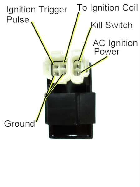
The next step will be to measure your stator ouputs (CDI power and CDI trigger) to see if they are working. But first look at the kill switch wiring.
Is this a picture of your CDI? If so, it will tell you which is the the kill switch wire. Most no spark issues are kill switch related.
The next step will be to measure your stator ouputs (CDI power and CDI trigger) to see if they are working. But first look at the kill switch wiring.
#3
09-20-2009, 06:23 PM
Join Date: Sep 2009
Posts: 9
Likes: 0
Received 0 Likes
on
0 Posts
I was finally able to get a chance to check this out. That is a pic of my cdi box. I checked the resistance two ways and came up with this. With the ignition switch on and the kill switch in the run position the meter goes up and says overload. With the switch in the kill engine position it reads .000. At no time whatever I do am I able to read power at the ignition pin. Should it read 12 volts? Help again please. Can I just put power to the ac ignition pin?
#4
09-20-2009, 08:04 PM
Electrical Expert
Likes High Voltage In The Tub!
Likes High Voltage In The Tub!
Join Date: Dec 2008
Location: Tracy, California, USA
Posts: 3,260
Likes: 0
Received 12 Likes
on
12 Posts
No!!! Don't do that. By power I'm assuming you mean 12 VDC from the battery. If you apply 12 volts DC to the AC power pin, and your CDI is AC powered, you will get a loud bang, lots of smoke, and a toasted CDI with a fresh new hole in it.
Testing for DC or AC CDI:
I'm pretty sure you have an AC powered CDI but lets make absolutely sure:
Unplug the CDI and measure the voltage on the pin labeled "AC Ignition Power" in the CDI wiring harness to engine ground. Set your meter to read DC volts on the 20 volt scale. If the pin measure 12 volts DC with the ignition on and zero volts with the ignition switch off then you have a DC powered CDI. They do make DC powered CDI's with the 4 pin and 2 pin connector configuration. Typically they are a little bigger than an AC version but otherwise look identical.
To see if you have an AC powered CDI, set you meter to AC volts on the 200 volt (or so) scale. Measure the same pin voltage to ground while cranking the engine. It won't start of course because the CDI is unplugged. You should measure 80 volts AC at cranking speeds. Note that this will be high voltage when the engine is turning, so watch your fingers while measuring this.
You should be able to verify one of the two configurations above. If not then we will need to do a couple more tests, but it also means that the problem is close at hand (i.e. you're not getting power to the CDI) and should be easy to pin down.
Other stuff to measure:
1) Measure the Ignition Trigger pin voltage to engine ground while cranking the engine. Set the meter to AC volts and put on the 1 volt (or so) scale. You should measure 0.3 to 0.5 volts AC while the engine is cranking. This test measures the signal voltage from the stator that tells the CDI when to fire the plug.
2) With the engine stopped measure the AC Ignition Power pin resistance to ground. It should read about 450 ohms. This measures continuity of the stator ignition power winding and associated wiring.
3) Do the same with the Ignition Trigger pin. It should read 140 ohms or so. This measures the continuity of the trigger winding also measured in test 1 above.
4) Do the same with the Ignition Coil pin. It should read about 2 ohms. This measures continuity of the ignition coil primary winding and associated wiring.
5) Measure the resistance of the spark plug cap wire to ground. It should read roughly 8000 ohms. This measures the continuity of the ignition coil secondary.
#5
09-24-2009, 06:12 PM
Join Date: Sep 2009
Posts: 9
Likes: 0
Received 0 Likes
on
0 Posts
#6
09-25-2009, 01:30 AM
Electrical Expert
Likes High Voltage In The Tub!
Likes High Voltage In The Tub!
Join Date: Dec 2008
Location: Tracy, California, USA
Posts: 3,260
Likes: 0
Received 12 Likes
on
12 Posts
Ok did some testing last night. I have 96 volts ac when cranking the engine. Of the other stuff to test I came up with this.
#1 ignition trigger pin 0.2 volts
#2 ac ignition power pin 1.359 ohms
#3 145.2 ohms
#41 ohm
#57.54 ohms
Thanks for helping so far.Help again please
#1 ignition trigger pin 0.2 volts
#2 ac ignition power pin 1.359 ohms
#3 145.2 ohms
#41 ohm
#57.54 ohms
Thanks for helping so far.Help again please
#1) Ignition trigger pin voltage is believable. This voltage is actually a fast and narrow +/- 5 volt up/down pulse happening only 10 times per second at cranking speeds. The long dead time time between pulses is averaged by most meters and so it reads much lower than the +/- 5 volt peak. And different meters read differently by a bit.
#2) Uh Oh. 1.359 ohms is highly suspect. Most ohmmeters don't have resolution out to milliohms (0.001 ohms). The resistance of the test leads themselves exceed that. Could you check that again? It should be in the hundreds of ohms - not down around 1 ohm.
#3) I can believe this. This also correlates with the measurement in #1 above. When measuring one parameter two different ways and the results line up like they should then that is a warm feeling.
#4) I hope you meant 1 ohm. That sounds good.
#5) Did you mean 7.54 Kiloohms (7.54K ohms or 7540 ohms)? Mine is 8K ohms (8000). But I have to say I've seen others post values in the 5 to 30 ohm range, but they also remove a cap resistor first. I'm sure I have a resistor too, but mine is not removeable.
Plug the CDI in and measure the kill switch pin to ground while cranking. Poke through the wire insulation to the copper core with a straight pin if you have to - just remember there may be high voltage on this pin so be careful. Measure both AC and DC voltages and report both. This peeks into the CDI internal high voltage supply and gives an indication whether it is working at least this far through the CDI.
#7
10-22-2009, 09:09 PM
Join Date: Sep 2009
Posts: 9
Likes: 0
Received 0 Likes
on
0 Posts
Trending Topics

Thread
Thread Starter
Forum
Replies
Last Post
fordfaithful21
Polaris Ask an Expert! In fond memory of Old Polaris Tech.
9
12-07-2015 05:52 PM
Cdenton
Technical and How-To Articles
1
09-09-2015 11:23 AM
Currently Active Users Viewing This Thread: 1 (0 members and 1 guests)