2007 sunL 110 with no spark...please help??
#11
 06-24-2010, 11:27 PM


Electrical Expert
Likes High Voltage In The Tub!
Likes High Voltage In The Tub!
Join Date: Dec 2008
Location: Tracy, California, USA
Posts: 3,260
Likes: 0
Received 12 Likes
on
12 Posts
Hey guys sorry i've been busy...We went and got a brand new battery...after charging it and everything we tested everything all over again and got the same results...which didn't make any sense to begin with...so my bro in law gave up and ordered a new stator and case...so we're waiting to get that in the mail...then we're gonna try the same tests all over again..
#12
06-27-2010, 10:34 PM

#13
10-07-2010, 03:19 PM

Just so I know where to start from, how exactly did you check the stator and the wiring? Is this a visual test, or did you use a meter? If you used a meter what values did you measure, and under what conditions were they measured?
How did you bypass the kill circuitry? The majority of times when someone says they "bypassed" something that means they shorted it out. In this case that would be 100% wrong. If you had said you "disconnected" the kill circuitry that would instill slightly more confidence.
No spark problems can be fixed. You need a meter, some guidance, and the ability to follow directions. Junking it would be a terrible idea.
I had the same problem. The place to disconnect the kill switch. Is located near the steering coloum. A small black box with 5 wires going in. To disconnect the kill switch remove the harness then push out the white and black wire with a small screw driver. Then check for spark. In my case it worked and quad fired right up. I now have to choke the carb to shut her down. zoom ZOOM
#14
10-07-2010, 09:16 PM

I had the same problem. The place to disconnect the kill switch. Is located near the steering coloum. A small black box with 5 wires going in. To disconnect the kill switch remove the harness then push out the white and black wire with a small screw driver. Then check for spark. In my case it worked and quad fired right up. I now have to choke the carb to shut her down. zoom ZOOM
#15
06-26-2011, 03:21 PM

Lynn:
Here are my readings based on the attached post:
AC ignition power pin to ground(cranking) 35 volts
Timing trigger pin to ground (cranking) .48 to .50 volts
AC ignition power pin to ground 0.372k ohms
Timing trigger to ground infinite or 1, no resistance
CDI ground pin to engine ground 0.6 ohms
Ignition coil pin to engine ground 0.8 ohms
I have already replaced CDI, spark plug and spark plug cable assembly.
Any ideas or suggestions would be appreciated!
This is the generic 5 pin CDI (so you don't have to go look it up):
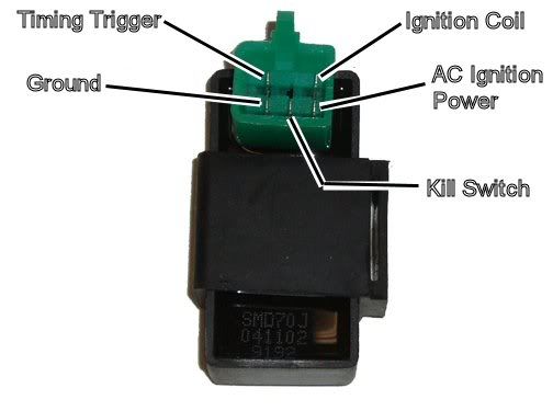
You've disconnected the kill switch wire in the wiring harness so it does not connect to the CDI (if I understand your post correctly). Therefore it cannot be a kill switch issue.
Set your meter to read AC volts on the 200 volt scale. Test your meter by sticking the probes into a wall power outlet in your house. You should see about 120 volts AC. If you get that you know your meter is set up properly and working.
Now disconnect the CDI from the quad wiring harness. Measure the AC voltage on the AC ignition power pin of the wiring harness to engine ground while cranking the starter motor. That will be putting one lead on the wiring harness pin, and the other lead on the the aluminum motor block. You should see 45 to 80 volts AC at normal cranking speeds. What do you measure?
Set your meter to the lowest AC voltage scale that is has. 2 volts AC full scale would be ideal but many meters don't go that low. Use whatever the lowest range is, but make sure it is AC volts and not DC volts. Measure the voltage on the timing trigger pin in the wiring harness to engine ground while cranking the starter. You should see 0.2 to 0.5 volts AC. What do you measure?
Set your meter to measure resistance (ohms) on the 2K ohms scale (2000 ohms). When on the resistance settings you should read zero ohms with the leads shorted, and infinite ohms when the leads are not connected together.
Turn off the quad ignition switch. Measure the AC Ignition Power pin on the wiring to engine ground with the engine sitting still (not cranking). You should see 450 ohms or so (0.450 Kohms). Measure the Timing Trigger line to ground. You should read 150 ohms or so (0.150 Kohms) with the engine sitting still. What do you measure for both of those pins?
Set your meter to the lowest resistance scale it has (20 ohms is about right).. Measure the resistance of the ground pin in the CDI to engine ground. It should read zero ohms. Measure the Ignition coil pin to engine ground. It should 0.5 ohms or so. It should not read zero ohms. Report back any descrepancies with these two values.
#16
06-26-2011, 04:11 PM
Electrical Expert
Likes High Voltage In The Tub!
Likes High Voltage In The Tub!
Join Date: Dec 2008
Location: Tracy, California, USA
Posts: 3,260
Likes: 0
Received 12 Likes
on
12 Posts
Lynn:
Here are my readings based on the attached post:
AC ignition power pin to ground(cranking) 35 volts
Timing trigger pin to ground (cranking) .48 to .50 volts
AC ignition power pin to ground 0.372k ohms
Timing trigger to ground infinite or 1, no resistance
CDI ground pin to engine ground 0.6 ohms
Ignition coil pin to engine ground 0.8 ohms
I have already replaced CDI, spark plug and spark plug cable assembly.
Any ideas or suggestions would be appreciated!
Here are my readings based on the attached post:
AC ignition power pin to ground(cranking) 35 volts
Timing trigger pin to ground (cranking) .48 to .50 volts
AC ignition power pin to ground 0.372k ohms
Timing trigger to ground infinite or 1, no resistance
CDI ground pin to engine ground 0.6 ohms
Ignition coil pin to engine ground 0.8 ohms
I have already replaced CDI, spark plug and spark plug cable assembly.
Any ideas or suggestions would be appreciated!
You measured signal on this wire, but that is likely just cross talk from adjacent wires. That can happen when the wire is open.
Before buying a new stator I would pop off the engine side cover and take a look for any obvious problems. The trigger signal comes from a small pickup coil mounted outside the flywheel. There is also a ground wire coming off the stator. Make sure it is grounded.
#17
06-26-2011, 07:59 PM
OK, I am having trouble locating "wiring harness at the stator". Not sure I have properly identified the stator. The timing trigger is a blue-white wire but I cannot locate a similar blue-white wire coming out of what I thought was the wiring harness for the stator.
When you said "you measured signal on this wire" which wire were you refering to?
Popping off the engine side cover? I am assuming this can be done by removing the large screw on the left side (as you are seated on the bike) of the engine? What would I be looking for inside the flywheel compartment? Thx
#18
06-27-2011, 12:47 AM
Electrical Expert
Likes High Voltage In The Tub!
Likes High Voltage In The Tub!
Join Date: Dec 2008
Location: Tracy, California, USA
Posts: 3,260
Likes: 0
Received 12 Likes
on
12 Posts
OK, I am having trouble locating "wiring harness at the stator". Not sure I have properly identified the stator. The timing trigger is a blue-white wire but I cannot locate a similar blue-white wire coming out of what I thought was the wiring harness for the stator.
When you said "you measured signal on this wire" which wire were you refering to?
Popping off the engine side cover? I am assuming this can be done by removing the large screw on the left side (as you are seated on the bike) of the engine? What would I be looking for inside the flywheel compartment? Thx
When you said "you measured signal on this wire" which wire were you refering to?
Popping off the engine side cover? I am assuming this can be done by removing the large screw on the left side (as you are seated on the bike) of the engine? What would I be looking for inside the flywheel compartment? Thx
1) Moderatly high voltage AC ignition power to the the CDI.
2) A small signal trigger signal that tells the CDI when to fire
3) A lower voltage high current winding used to charge the battery back up and run the headlights.
Important: Don't look at the wire colors of the wires coming out of the engine. They could be anything, and are completely irrelevant. Look at the colors of the wires in the main wiring harness that the stator wires connect to. The idea here is that a blue white wire at the CDI connector in the main wiring harness is still a blue white wire when it emerges at the stator connector(s). See the logic? You don't need to untape the whole wiring harness to follow a wire to where is goes. Just look for the same color at each end, and then hust to be sure verufy it with a continuity check with you ohm meter.
You measured a signal of the timing trigger wire of ".48 to .50 volts". That is what I was referring to. You can't have a real legitimate signal on this wire if the pickup coil is open. Thus I suspect that this signal level is just stray pickup from adjacent wires in the harness - which happens on open wires with a very high impedance to ground. It doesn't happen on a working quad with 150 ohms to ground through the pickup coil.
I am sure you have to remove more than one big screw to get the side engine cover off. I've never owned a 110cc and have never done it myself, though I'm sure it is not hard. Inside the cover you will see a pickup coil outside the flywheel. The other two coils will be inside the flywheel. The flywheel is pressed on and will require a puller to remove. I would be looking at the wiring to the trigger coil and any ground return wires.
#19
06-27-2011, 12:19 PM

On your 110 it's a 2 coil design, i assume a BMX engine (if it's the same engine I have)
To remove the stator cover, take the gear shifter off (one bolt on the shaft)
then 4 bolts holding the cover on.
When you ordered the new stator and cover, did you order a gasket with that? If the chain came off and cracked the housing like it did mine, the old gasket is going to be really messed up.
It may also help if you remove the chain guard (2 bolts)
The gear shifter is a 10mm and all the other ones are 8mm
as for wireing and voltage, well i'm no good at that. i just know how to take it apart.
#20
06-28-2011, 08:16 PM
OK, I went back and checked the timing trigger wire (blue and white) between the CDI and the stator. Sure enough, the bullet connection into the stator was disconnected! I connected the wires with the bullet connector and then went back and checked resistance to ground at the CDI wiring harness. I have a reading of 127 ohms at the timing trigger pin. I turned on ignition and tried to start the ATV. It still won't fire! Any other ideas?
The stator is a set of three coils located inside the engine. So what you are looking for is a bunch of wires emerging out of the engine side cover. These wires will only travel a short distance before they terminate in a connector (and often some individual single wire "bullet" connections). The three stator coil functions are:
1) Moderatly high voltage AC ignition power to the the CDI.
2) A small signal trigger signal that tells the CDI when to fire
3) A lower voltage high current winding used to charge the battery back up and run the headlights.
Important: Don't look at the wire colors of the wires coming out of the engine. They could be anything, and are completely irrelevant. Look at the colors of the wires in the main wiring harness that the stator wires connect to. The idea here is that a blue white wire at the CDI connector in the main wiring harness is still a blue white wire when it emerges at the stator connector(s). See the logic? You don't need to untape the whole wiring harness to follow a wire to where is goes. Just look for the same color at each end, and then hust to be sure verufy it with a continuity check with you ohm meter.
You measured a signal of the timing trigger wire of ".48 to .50 volts". That is what I was referring to. You can't have a real legitimate signal on this wire if the pickup coil is open. Thus I suspect that this signal level is just stray pickup from adjacent wires in the harness - which happens on open wires with a very high impedance to ground. It doesn't happen on a working quad with 150 ohms to ground through the pickup coil.
I am sure you have to remove more than one big screw to get the side engine cover off. I've never owned a 110cc and have never done it myself, though I'm sure it is not hard. Inside the cover you will see a pickup coil outside the flywheel. The other two coils will be inside the flywheel. The flywheel is pressed on and will require a puller to remove. I would be looking at the wiring to the trigger coil and any ground return wires.