looking for wiring dirgram for vli150st?
#1
 06-20-2010, 09:50 PM


Join Date: Jun 2010
Posts: 5
Likes: 0
Received 0 Likes
on
0 Posts
Hi I am new my atv won't start, cranks but no spark. It has 6 pin cdi with only four wires to it. Four from the stator I don't know how may coils. The ATV is a VLI 150 ST (Veleer Industries LLC) I can't find a wiring diagram for it and the dealer is out of business. It has a gy6 1p57qmj 149cc engine.
any help welcomed
thanks
Garcia
any help welcomed
thanks
Garcia
#2
06-21-2010, 12:24 AM

Electrical Expert
Likes High Voltage In The Tub!
Likes High Voltage In The Tub!
Join Date: Dec 2008
Location: Tracy, California, USA
Posts: 3,260
Likes: 0
Received 12 Likes
on
12 Posts
I've not seen a wiring diagram for your quad, but I really don't think having one is essential to troubleshooting the problem.
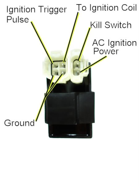
Does the above picture look like your CDI? If yes, then some tests:
1) You have only four wires hooked up to the CDI. That means you have a DC powered CDI. The AC Ignition Power pin will be hooked to 12 volts DC battery power when the ignition switch is on and all kill switches are off. Verify this with a voltmeter by unplugging the CDI and measuring the power pin in the wiring harness to ground on the DC 20volt scale on your meter. Again, the ignition switch is must be on and all kill switches are off ("run" position). When you measure this do you see 12 volts DC?
2) Switch to AC volts on the lowest scale possible. 2 volts would be ideal, but some meters only measure AC volts down to 200 volts. Measure the AC voltage to ground while cranking the engine. You should see about 0.2 to 0.4 volts AC. Again the ignition switch is on and all kill switches off (in the "run" position). What do you measure?
3) Switch the meter to measure resistance (in ohms) on the 2000 ohm scale (also labeled as 2K ohms). Measure the same pin's resistance to ground (same setup as before). You should see 140 ohms or so. What do you measure?
4) Measure the resistance from the ground pin in the wiring harness to engine ground (still same setup as before). You should measure zero ohms. What do you measure?
5) Set your meter to AC volts again on the 200 volts AC scale. Plug the CDI back in for this test. Otherwise the setup is the same (ignition on, kill switch off (run position). Measure the ignition coil pin voltage to ground while cranking the engine. You should see mostly zero readings with random numbers in between. Crank the engine for ten seconds. Do you see the pattern described above? What is the highest voltage you saw?
All these measurement are on the CDI. There is a reason for this: The CDI sits smack dab in the middle of the ignition system. By looking carefully here we can find out which input/output line isn't right and follow it back from there.
#3
06-21-2010, 09:35 PM
Join Date: Jun 2010
Posts: 5
Likes: 0
Received 0 Likes
on
0 Posts
#4
06-21-2010, 11:45 PM
Electrical Expert
Likes High Voltage In The Tub!
Likes High Voltage In The Tub!
Join Date: Dec 2008
Location: Tracy, California, USA
Posts: 3,260
Likes: 0
Received 12 Likes
on
12 Posts
1) Good, that verifies your CDI is a DC powered version.
2) Wrong. This signal line tells the CDI when to fire. It is actually a pair of narrow plus/minus pulses about 5 volts peak at cranking speeds with lots of nothing (zero volts) inbetween. Meters aren't designed to measure this kind of complicated waveform, hence they tend to average down to a very low voltage. But you should measure something like 0.2 to 0.4 volts AC. Just in case you're curious, this is what the voltage looks like on an oscilloscope at cranking speeds:
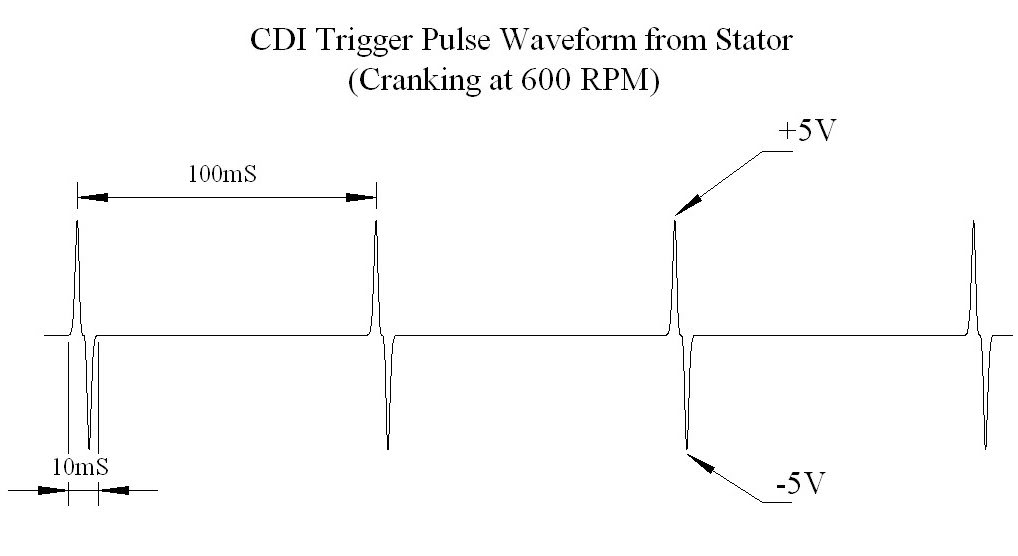
3) Wrong. This is just another way of measuring #2 above. And your answer here is compatible with your answer in #2. The timing trigger signal voltage is generated by a small pickup coil mounted outside the flywheel. As a raised bump on the flywheel passes under the pickup coil it distorts a magnetic field inside the pickup coil and generates the voltage waveform in the above picture (the magnet is inside the pickup coil). The plus pulse is the leading edge of the raised bump, and the negative pulse is the trailing edge of the raised bump.
4) This reading is wrong and does not make sense in any way I can think of. This wire should be zero ohms to ground in order for the CDI to work and make spark. But occasionally quad vendors will kill spark by removing the ground to the CDI. This isn't a common way to kill spark, but its possible so lets keep it in mind. More likely is that you measured something wrong, so could you please recheck this? Again, kill switches in the run position, and ignition on.
The difficulty with this measurement is the 11.2 ohms. That's the part I can't explain quite yet. If it is still 11.2 ohms on remeasure then report back and we'll dig in deeper.
5) Your measurements indicates that no large narrow high voltage pulses are being sent to the coil. # 1 and #2 above indicate you aren't getting a trigger, so you'd expect that nothing will be coming out of the CDI.
So you aren't getting a trigger pulse, and there is a mystery about the ground wire to the CDI.
A) Find the wires coming out of the stator (wires coming out of the engine). There should be four. What are their colors? When you answer this use the wire colors in the wiring harness and not the pigtails coming out of the stator.
What we are trying to do is separate the battery charge winding wires (usually yellow and white) from the trigger wire (usually blue/white) and ground (usually green or black). Then we can look at the trigger voltage at the output of the stator.
B) If you really do see 11.2 ohms on the ground wire to engine ground then try grounding it with a jumper. Do you get spark then? Problem here is that you may have two problems. You need a trigger signal *and* a ground connection at the CDI for spark to occur. I'd concentrate on getting a trigger signal voltage first, then making a good ground.
One final note: To shut a quad off you need to stop the spark. That's done with the ignition switch and/or kill switches. On a DC powered CDI the ways to kill a spark are:
I) Remove DC power to the CDI.
II) Remove the CDI ground.
III) Disconnect the timing trigger signal from the stator to the CDI.
IV) Short the Timing trigger to ground
Now you can see why I was so careful about specifying that the ignition switch is on and the kill switches set to "run". It would be a minor wild goose chase to follow a missing voltage back only to find the kill switch is in the "stop" position or the ignition switch is off, and that this has nothing to do with the real problem.
#5
06-22-2010, 08:55 PM
Join Date: Jun 2010
Posts: 5
Likes: 0
Received 0 Likes
on
0 Posts
A. Stator wire colors on the engine side of the harness, (blue/white stripe, green, yellow, white)
B. Measured today was 4.5 ohms
I checked voltage while cranking on the trigger wire (blue/white to green in the stator pigtail) reading was 40 mv
I do understand what the stator voltage signal looks like. I took some electronics courses in high school (a long time ago though).
Garcia
B. Measured today was 4.5 ohms
I checked voltage while cranking on the trigger wire (blue/white to green in the stator pigtail) reading was 40 mv
I do understand what the stator voltage signal looks like. I took some electronics courses in high school (a long time ago though).
Garcia
#6
06-23-2010, 12:02 AM
Electrical Expert
Likes High Voltage In The Tub!
Likes High Voltage In The Tub!
Join Date: Dec 2008
Location: Tracy, California, USA
Posts: 3,260
Likes: 0
Received 12 Likes
on
12 Posts
This is still not right. 4.5 ohms is too much, and its value shouldn't change between measurements. So if you take your meter and set it to the lowest ohms scale and short the meter leads, does it read zero ohms then?
If you do need to change the stator you will need a puller to remove the flywheel. BuggyDepot.com had inexpensive pullers when I last looked. You might try eBay as well. Also note that stators come in 6 pole and 8 pole versions. Make sure that you get the one that matches your current setup. If you combine a six pole stator with an eight pole flywheel (or vice versa) your battery charging system will flat out not work.
I could tell. I wouldn't have posted the waveforms if I thought it would just further confuse the situation....
#7
06-23-2010, 09:57 PM
Join Date: Jun 2010
Posts: 5
Likes: 0
Received 0 Likes
on
0 Posts
Lynn,
I had already pulled the fan cover and the fan to check for broken wires before I aksed for help. All looked OK. So I pulled the flywheel and stator so I could get a good look at it.
There are no broken wires or lose solder joints on the stator.
I measured restience on all wires from the pigtail to the solder joint all were measured on a 200 ohm scale they read .3 ohms
I checked to see if any where shotred to ground ( white, yellow ) they were open. Green had continuity to the stator mounting surface. The blue/white measured pigtail to mounting bracket of the trigger coil which mounts to the engine 126.4 ohms.
The meter I was first using was autoranging todays measurements were on a conventional meter.
Garcia
Trending Topics
#8
06-23-2010, 11:42 PM
Electrical Expert
Likes High Voltage In The Tub!
Likes High Voltage In The Tub!
Join Date: Dec 2008
Location: Tracy, California, USA
Posts: 3,260
Likes: 0
Received 12 Likes
on
12 Posts
Lynn here are the answers to your questions
1. 12 volts dc
2. 0.0 volts ac
3. open inifinity
4. 11.2 ohms
5. no pattern 0.0 volts ac
the cdi looks similar its a zonko
The goal is to find some point where the trigger connection goes from 130 ohms to open, and then focus there.
I keep meaning to ask (and I keep forgetting): What is a "zonko" CDI?
#9
06-24-2010, 05:47 PM
Join Date: Jun 2010
Posts: 5
Likes: 0
Received 0 Likes
on
0 Posts
Lynn I put it back together slowly as you said checking to see I still had the readings. Got it all back together all was OK so I checked spark had spark. Next see if it will run (had to put fuel tank back on now no spark). Let it sit a while to think about it (what did I move). I came back to it a couple hours later and spark put plug back in and it started. I have a faulty connection some place in there I will have to keep looking for it. Thank you for all your help.
Best regards Garcia
Best regards Garcia
#10
06-24-2010, 11:20 PM
Electrical Expert
Likes High Voltage In The Tub!
Likes High Voltage In The Tub!
Join Date: Dec 2008
Location: Tracy, California, USA
Posts: 3,260
Likes: 0
Received 12 Likes
on
12 Posts
Garcia,
Well I'm glad it is sort of running . Problem is that it will probably only quit when you're way out there somewhere in the bottom of a canyon. Intermittents are hard to isolate and fix.
Don't forget that your CDI ground wire resistance was flakey too. It is possible that you've fixed the trigger problem and now whether you get spark or not is being determined by the quality of your CDI ground wire. Maybe a preemptive action is in order, where you just bypass the flakey ground wire with a new one.
Lynn
Well I'm glad it is sort of running
. Problem is that it will probably only quit when you're way out there somewhere in the bottom of a canyon. Intermittents are hard to isolate and fix.Don't forget that your CDI ground wire resistance was flakey too. It is possible that you've fixed the trigger problem and now whether you get spark or not is being determined by the quality of your CDI ground wire. Maybe a preemptive action is in order, where you just bypass the flakey ground wire with a new one.
Lynn

Thread
Thread Starter
Forum
Replies
Last Post
Currently Active Users Viewing This Thread: 1 (0 members and 1 guests)