Cdi box circuit help needed
#1
 06-12-2011, 06:05 PM


Join Date: Jun 2011
Posts: 8
Likes: 0
Received 0 Likes
on
0 Posts
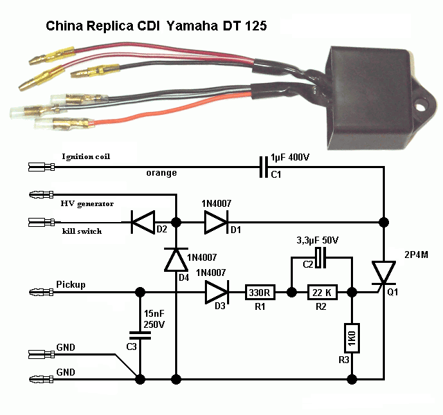
Hi i am building A cdi unit designed for Yamaha dt125 but will be using it for my quadzilla ram r100 (2 stroke 100cc rev n go). I have taken apart the old cdi unit and looked at the circuit board and it matches the Yamaha dt125 circuit diagram.
My old cdi unit contains:
-transistor scr = t106m2 (still have it but taken off the board for replacement)
-diodes =1n4007 (taken off the board thrown away they cheap to buy, there was one odd one that had no writing on it maybe text rubbed off)
-capacitor = 400v 1uf (thrown away drilled through it)
-capacitor = labeled 153 (i think is 15nf 1000v)
-cap = 2.2uf 50v (thrown away drilled through it)
-resistors = 33k, 1k, 300r
But i be modifying the old circuit board with new parts from the diagram:
Circuit diagram is provided below:
Now my question??
1.what diode is the D2?
2. what alternative transistor can i use apart from 2p4M?
i am desperate to get the quad started but 40 quid a cdi unit i rather build one. I will be hopefully reporting back if it works or not.
Thank you
#2
06-12-2011, 11:25 PM

Electrical Expert
Likes High Voltage In The Tub!
Likes High Voltage In The Tub!
Join Date: Dec 2008
Location: Tracy, California, USA
Posts: 3,260
Likes: 0
Received 12 Likes
on
12 Posts
The diode D2 can just be another 1N4007.
The SCR is usually a 600 volt 6 or 8 amp sensitive gate device. The CDI's I've taken apart have all used SX405MF in a TO220 package. This device must be heat sunk of course.
Don't skimp on the C1 capacitor. This device has a very high ripple current. Use a metalized film capacitor (mylar or polypropylene dielectric) that is designed for pulsed AC applications. If you cheap out here you will have a CDI that doesn't last very long.
#3
06-13-2011, 08:03 AM
Join Date: Jun 2011
Posts: 8
Likes: 0
Received 0 Likes
on
0 Posts
I have purchased these capacitors they are polypropylene 400v 1uf mkt.
10x 1uF 400V Polypropylene Capacitors (Free P&P) on eBay (end time 26-Jun-11 20:36:18 BST)
SX405M i cant seem to find on ebay or anything comes up on google
what about bt151 they are around like 7.5a 500v.
picture of the cdi circuit is uploaded.
http://imageshack.us/photo/my-images/824/53273426.jpg/
http://imageshack.us/photo/my-images/196/27029566.jpg/
#4
06-13-2011, 11:14 PM
Electrical Expert
Likes High Voltage In The Tub!
Likes High Voltage In The Tub!
Join Date: Dec 2008
Location: Tracy, California, USA
Posts: 3,260
Likes: 0
Received 12 Likes
on
12 Posts
The capacitor is probably fine.
The SCR will fire and generate spark, but my worry is that the ignition timing may not be quite right as you throttle up. The ignition timing has to advance as the engine speed increases. The CDI accomplishes this by conditioning the trigger signal which gets higher in amplitude, and higher in frequency as the engine speed throttles up.
You may need to adjust the values for R1-R3 and C2 to get the timing advance right for the new SCR. But then again maybe it will work. Try it and see...
#5
06-14-2011, 10:07 AM
Join Date: Jun 2011
Posts: 8
Likes: 0
Received 0 Likes
on
0 Posts
My biggest problem is wiring the quad up becuase if i am going to add parts to circuit board or make another one then i also must figure out how the quad is wired up.
I need to get quadzilla ram 100c diagram wiring with color code of wires to make it easier for me to understand because my suspicion is its either the wiring or cdi.
my wiring says this on cdi circuit board :
1.SO - black/red wire
2.PU - Orange/white wire
(no: 1, 2 are in a tab together that clips into the stator i think)
3.GND -black wire
4.e/s or c/s as the text is worn from scraping off silicone - black/white wire
5.ION or IGN (text is worn) - Orange wire i think this goes straight to the ignition coil.
3,4,5 all are in a tab that clips on the other half of the wire in the quad harness.
i need a quadzilla r100 diagram of wiring with color code or labels of color becuase i rather start from scratch and make my own harness.
#6
06-14-2011, 11:53 PM
Electrical Expert
Likes High Voltage In The Tub!
Likes High Voltage In The Tub!
Join Date: Dec 2008
Location: Tracy, California, USA
Posts: 3,260
Likes: 0
Received 12 Likes
on
12 Posts
My comments embedded in Blue:
Do you have any wiring harness at all? Wiring up quad is a lot of work. I would opt to fix the old harness rather then come up with a new one altogether.
I don't have a specific diagram for your quad, but there are only a few variations on how to wire it up. If you're wiring up the whole quad from scratch then you can wire it up many different ways. If you're salvaging the existing wiring harness (my first choice) then you tackle one circuit at a time. For each circuit section you make a few measurements to determine which wiring scheme is being used (with help of course), fix that section, then move on to the next. For an example of how to break this down into smaller chunks:
1) Get the battery turning the starter with the start button,
2) then get spark,
3) then get the quad running and shutting down properly,
4) then get the battery charging circuitry working,
5) then get ancillary stuff like lights and stereo working.
My biggest problem is wiring the quad up becuase if i am going to add parts to circuit board or make another one then i also must figure out how the quad is wired up.
I need to get quadzilla ram 100c diagram wiring with color code of wires to make it easier for me to understand because my suspicion is its either the wiring or cdi. [I would have done some measurements on the wiring before ripping apart the CDI]
my wiring says this on cdi circuit board :
1.SO - black/red wire [HV Generator - goes to stator]
2.PU - Orange/white wire [Pickup - goes to stator]
(no: 1, 2 are in a tab together that clips into the stator i think)
3.GND -black wire
4.e/s or c/s as the text is worn from scraping off silicone - black/white wire [kill switch - goes to kill switch wiring - ground this pin to kill engine]
5.ION or IGN (text is worn) - Orange wire i think this goes straight to the ignition coil. [Goes to ignition coil primary]
3,4,5 all are in a tab that clips on the other half of the wire in the quad harness.
i need a quadzilla r100 diagram of wiring with color code or labels of color becuase i rather start from scratch and make my own harness.
I don't have a specific diagram for your quad, but there are only a few variations on how to wire it up. If you're wiring up the whole quad from scratch then you can wire it up many different ways. If you're salvaging the existing wiring harness (my first choice) then you tackle one circuit at a time. For each circuit section you make a few measurements to determine which wiring scheme is being used (with help of course), fix that section, then move on to the next. For an example of how to break this down into smaller chunks:
1) Get the battery turning the starter with the start button,
2) then get spark,
3) then get the quad running and shutting down properly,
4) then get the battery charging circuitry working,
5) then get ancillary stuff like lights and stereo working.
#7
06-15-2011, 04:01 PM
Join Date: Jun 2011
Posts: 8
Likes: 0
Received 0 Likes
on
0 Posts
Got it working for at least 20 minutes it didn't start again it just went off itself. i even had the 2p4m (2a 400v)scr heat sinked and insulated heavily . i think the original t106m2 was around 600v or 400v 4amps. caps were abit bigger for example 1uf 400v was replaced with 1.5 uf 400v polypropylene and 2.2uf was replaced with 3.3uf cap and fresh new 1n4007 diodes. i think i burnt the transistor but i dont get it why maybe it couldn't handle the volts/amps i have ordered bt151 transistor 500v 7.5a now.
Trending Topics
#8
06-15-2011, 11:38 PM
Electrical Expert
Likes High Voltage In The Tub!
Likes High Voltage In The Tub!
Join Date: Dec 2008
Location: Tracy, California, USA
Posts: 3,260
Likes: 0
Received 12 Likes
on
12 Posts
So see what failed. The two parts that have the most stress on them are the SCR, and the capacitor C1. Also look for bad solder joints, etc.
1.5 uF instead of 1.0 uF will affect spark performance. C1 is part of a resonant circuit. This capacitance is charged up to a hundred or few volts, then connected across the coil primary by the SCR when the plug is fired. The capacitor and the ignition coil primary winding inductance form a resonant circuit which rings at its resonant frequency (about 30 KHz). The coil secondary winding is also resonant at some frequency due to its inductance and the distributed interwinding capacitance. These two resonant frequencies are supposed to match. That way you get maximum energy transfer between the two ignition coil windings (primary and secondary). By changing the value of C1 you have altered that "match" and affected the amount of spark energy that can be delivered to the plug.
I don't know if you're familiar with the old Kettering style ignition common on cars in the 1960's, where the coil was charged up (with a magnetic field) from current switched in with a set of "points" (just a mechanical switch). At the proper time the points opened, and the charged up ignition coil primary resonanated with a capacitor (often called a "condenser") across the points (switch), which resonated with the coil secondary. This works exactly the same as with newer CDI ignition systems. With the Kettering ignition systems both the points and condenser were high wear/failure items and were replaced routinely during a tune up. The value of the condensor was important. If you had a chevy impala you wouldn't try to put in a ford falcon condensor. You used the right part. The basic principle of operation between these two systems is pretty much the same. The old kettering style ignition charged up the ignition coil primary with a magnetic field before letting it ring back and forth with the condenser (capacitor). The CDI charges up the capacitor (condensor) before letting it ring back and forth with the ignition coil primary inductance. Same thing. CDI's out perform Kettering ignition system at high speed because it is easier to charge a capacitor quickly (with voltage) then it is to charge up a coil (with a magnetic field). Hence CDI systems won out over time.
The value of C2 (and the SCR, and other parts in and around there) will most likely affect ignition timing at speed. This is important to pay attention to. You've transistoned over into a "development engineering" role instead of a "just fix this quad" role. I don't want to discourage you (learning is great) but want to make sure you realize that this may not be as easy as you think.
#9
06-16-2011, 06:34 AM
Join Date: Jun 2011
Posts: 8
Likes: 0
Received 0 Likes
on
0 Posts
#10
06-18-2011, 05:27 PM
Join Date: Jun 2011
Posts: 8
Likes: 0
Received 0 Likes
on
0 Posts
right i think my spark plug coil is faulty or i need new stator ignition coil.
i have seen stator coil on eBay but for 80 quid it a ripp off
Quadzilla SMC R100 Quad ATV Stator | eBay UK.
can anyone give me list of stator coil from various makes and models that also fit the quadzilla r100. for example Honda bike use same parts regardless size of engine etc.
i have seen stator coil on eBay but for 80 quid it a ripp off
Quadzilla SMC R100 Quad ATV Stator | eBay UK.
can anyone give me list of stator coil from various makes and models that also fit the quadzilla r100. for example Honda bike use same parts regardless size of engine etc.