Linhai 300cc No spark
#1
 08-20-2012, 09:12 PM


Hello. I have a 300cc Linhai that is about to drive me crazy. I have done everything I can think of with this thing trying to get it to spark. Still nothing. I have installed a new coil and CDI. Tested the stator coil and it tests OK. (0.18 ohms) Tested the ignition switch (even bypassed it with a jumper) Disconnected the kill switches wire from the CDI. And spent two hours+ looking at every wire and plugin to make sure nothing is loose or broken. Still no spark. Anyone have any ideas? Or maybe a spare stick of dynamite?
The following users liked this post:
jc4wd11 (12-19-2021)
#2
08-21-2012, 01:50 AM

Electrical Expert
Likes High Voltage In The Tub!
Likes High Voltage In The Tub!
Join Date: Dec 2008
Location: Tracy, California, USA
Posts: 3,260
Likes: 0
Received 12 Likes
on
12 Posts
I've never seen a 300cc Linhai quad.
How many pins on your CDI? Can you post a picture (or a link to a picture of your CDI)? What are the wire colors going to your CDI?
How may wires coming out of your stator? What are their colors (on the wiring harness side of any connector near the stator.)?
How many pins on your CDI? Can you post a picture (or a link to a picture of your CDI)? What are the wire colors going to your CDI?
How may wires coming out of your stator? What are their colors (on the wiring harness side of any connector near the stator.)?
#3
08-21-2012, 09:06 AM
The stickers all over the plastic body say 300. But it could very well be a 260cc.
It has 8 pins but it is only using 5 of them.
Yes.  Black/Yellow - Green - Blue/Yellow - Black/Red - Pink (I unhooked the pink to bypass all the kill switches but still no spark)
5
3 all yellow wire together going to the voltage regulator. 2 wires coming from the stator (exciter) coil. One wire is yellow and the other is blue and yellow. These test at 0.18 ohms.
Thank you for helping.
How many pins on your CDI?
Can you post a picture (or a link to a picture of your CDI)?
What are the wire colors going to your CDI?
How may wires coming out of your stator?
What are their colors (on the wiring harness side of any connector near the stator.)?
Thank you for helping.
#4
08-21-2012, 09:16 AM
#5
08-21-2012, 08:23 PM
I think everything there is OK. I unplugged, cleaned, and checked all the plugs there for loose wires and/or bent or broken prongs. I didn't see anything wrong there that I didn't fix.
The headlights on this thing do come on whenever I turn on the ignition switch, even if I have the headlight switch in the off position. I unplugged the headlights so they would not run my battery down while I am trying to fix the spark problem.
I thought maybe the ignition switch might have been malfunctioning so I unplugged it and jumped the two red wires together with a jumper. Still just turned over with no spark.
Is there any wire or plug in particular you are thinking of? I would be very happy to recheck. It is definitely possible I might have overlooked something.
#7
08-21-2012, 11:52 PM
Electrical Expert
Likes High Voltage In The Tub!
Likes High Voltage In The Tub!
Join Date: Dec 2008
Location: Tracy, California, USA
Posts: 3,260
Likes: 0
Received 12 Likes
on
12 Posts
Trending Topics
#8
08-22-2012, 11:42 PM
Electrical Expert
Likes High Voltage In The Tub!
Likes High Voltage In The Tub!
Join Date: Dec 2008
Location: Tracy, California, USA
Posts: 3,260
Likes: 0
Received 12 Likes
on
12 Posts
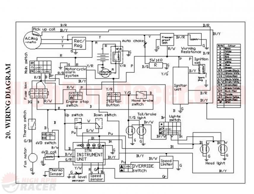
Looking around at various wiring diagrams I came across this for a Buyang 300cc quad (click on the thumbnail picture for a larger image):
The wire colors seem to match your quad, plus when I search vendors for Buyang 300cc CDIs I get pictures of 8 pin CDIs looking much like yours. So I'm hoping we can use this diagram as a template.
Note: This ignition topology is *totally* different from generic 150cc/110cc chinese quad wiring. If your quad wiring is similar to the Buyang wiring we're going to have to forge new paths through this unexplored territory, and throw away all your previously conceived notions from the more common generic chinese quad posts.
1) So unplug the CDI, turn on the ignition, and make sure the kill switch is in the "run" position. Use a meter to measure the voltage on the pink wire in the harness to ground and/or the green wire in the harness. You should see 12 volts DC. Do you? If you can follow the wiring diagram, note how this pink wire supplies the power (12 volts DC) to the CDI so it won't work without it. If you disconnect the pink wire you shut down the entire ignition system. Also note that this power flows through the kill switch, so it must be *shorted* when in the "run" state. If you put the kill switch in the "off" state the switch is open - disconnecting power to the CDI and shutting it down.
2) Measure the resistance of the black/yellow wire to ground (or the green wire) in the CDI harness connector. You should see something like 0.5 ohms. Tell me what you measure...
3) On your stator wires you claim three yellow (all battery charge related - and *not* related to spark so we can ignore them for now), plus a blue/yellow and another yellow. I'm wondering about that... Are you sure those other two wires aren't blue/yellow and black/red? Please check again.
4) WHere exactly are you measuring 0.18 ohms? Where are you putting the red lead? Where are you putting the black lead? What meter are you using? Tell me in detail where the switch setting is on your meter. The reason I'm focusing in here is because this reading sounds very wrong...
#9
08-24-2012, 10:21 PM
Looking around at various wiring diagrams I came across this for a Buyang 300cc quad (click on the thumbnail picture for a larger image):
Attachment 6556
The wire colors seem to match your quad, plus when I search vendors for Buyang 300cc CDIs I get pictures of 8 pin CDIs looking much like yours. So I'm hoping we can use this diagram as a template.
Attachment 6556
The wire colors seem to match your quad, plus when I search vendors for Buyang 300cc CDIs I get pictures of 8 pin CDIs looking much like yours. So I'm hoping we can use this diagram as a template.
I think the start switch cluster is a little different but everything else looks to match.
Note: This ignition topology is *totally* different from generic 150cc/110cc chinese quad wiring. If your quad wiring is similar to the Buyang wiring we're going to have to forge new paths through this unexplored territory, and throw away all your previously conceived notions from the more common generic chinese quad posts.

1) So unplug the CDI, turn on the ignition, and make sure the kill switch is in the "run" position. Use a meter to measure the voltage on the pink wire in the harness to ground and/or the green wire in the harness. You should see 12 volts DC. Do you?
If you can follow the wiring diagram, note how this pink wire supplies the power (12 volts DC) to the CDI so it won't work without it. If you disconnect the pink wire you shut down the entire ignition system. Also note that this power flows through the kill switch, so it must be *shorted* when in the "run" state. If you put the kill switch in the "off" state the switch is open - disconnecting power to the CDI and shutting it down.
2) Measure the resistance of the black/yellow wire to ground (or the green wire) in the CDI harness connector. You should see something like 0.5 ohms. Tell me what you measure...
3) On your stator wires you claim three yellow (all battery charge related - and *not* related to spark so we can ignore them for now), plus a blue/yellow and another yellow. I'm wondering about that... Are you sure those other two wires aren't blue/yellow and black/red? Please check again.
4) WHere exactly are you measuring 0.18 ohms?
Where are you putting the red lead?
Where are you putting the black lead?
What meter are you using?
Tell me in detail where the switch setting is on your meter.
Other readings on the same wires are as follows.
With the ohms on 2000k - it reads 000
On 200k - it reads 00.1
On 2000 - it reads 200
On 200 - it reads 1
The reason I'm focusing in here is because this reading sounds very wrong...
Thank you again for all your help!
#10
08-25-2012, 01:50 AM
Electrical Expert
Likes High Voltage In The Tub!
Likes High Voltage In The Tub!
Join Date: Dec 2008
Location: Tracy, California, USA
Posts: 3,260
Likes: 0
Received 12 Likes
on
12 Posts
I'm going to embed my responses within yours in the color blue...
Unplug the stator from the wiring harness. Measure the resistance looking into the stator between the blue/yellow and the yellow wire (which hooks to black/red in the harness). Use the 2000 ohm (2K ohm) scale. What do you measure?
Plug the stator back into the harness, and unplug the CDI. Put the kill switch into the run position, and crank the quad attempting to start it up while doing the following test (it won't start of course with the CDI disconnected):
1) Set your meter to measure AC volts on the lowest scale you have. Hopefully this will be 2 volts or 20 volts. Measure the voltage between the black/red and the blue/yel wire. What do you measure?
Now plug the CDI back in, and set your meter to measure AC voltage on the 20 volt scale.
2) Crank the engine as before, measuring the voltage on the black/yellow wire relative to the positive battery terminal. In other words, put your red lead on the black/yellow wire, and the black lead on the positive battery post. What do you measure? Reverse the meters leads and repeat the test. Do you get the same readings? This latter part of test 2 is testing the veracity of your meter, and your measurement technique. They should read exactly the same. If they don't be sure to say so...
Yes. I have checked quite a bit of the wiring and this is very close if not exact. It is much better than the one I was using.
I think the start switch cluster is a little different but everything else looks to match.
New frontiers.
I actually get 12.15 volts at the battery but only 11.87 volts on the pink and ground. [This is unimportant to the problems at hand. 11.87 volts is sufficient to run the DC powered CDI]
Yes I see that. It still will not spark with it connected though. Is there a wire I can disconnect to disable all of the kill switches? I had a wiring diagram that showed the pink as the kill switch wires but the one you posted is different. [Your kill switch is different if it is the same as the buyang 300 wiring. In this case the switch is closed (terminals connected) to enable spark. When in the "run" or "spark enabled" mode the switch provides 12 volt power to the CDI. When it is open (disconnected) the power to the CDI is removed, and spark is stopped. You already mostly determined that the kill switch is working by measuring 12 volts at the CDI connector. But just to be sure and nail this down completely, measure the pink wire to ground with the CDI hooked up. If you still get 12 volts when the kill switch in in the "run" position, and 0 volts with the kill switch in the "off" position, then you've determined that the switch is wired like we think it is wired, and that the kill switch is good.]
On all settings on the ohm meter I get 1 on those two wires. If I flip the selector onto 20k from one of the other settings, it flashes 19.75 or very close for a fraction of a second but then goes to 1. [Uh oh. I completely messed up when I told you how to do this test. This ignition system is different. The ignition coil primary winding (what we were trying to measure) is wired from the CDI output to +12 volts (the pink wire) - not ground (green wire) like most chinese quads. I told you wrong. So redo the test but measure from the black/yellow wire to the pink wire this time. My bad... ]
]
The wires come out of the stator as 1 blue/yellow and 1 solid yellow and go to the stator plugin on the stator side. On the wire harness side the wires are blue/yellow and black/red. [yes, that matches the wiring diagram for the Buyang 300. This is looking hopeful...]
On the plugin coming out of the stator, on the stator side.
On the yellow wire that becomes the black/red wire.
On the yellow/blue wire.
It is a Craftsman 82141 Digital Multimeter.
To get the reading of 0.18 I had the meter set to 20k on the ohms side.
Other readings on the same wires are as follows.
With the ohms on 2000k - it reads 000
On 200k - it reads 00.1
On 2000 - it reads 200
On 200 - it reads 1 [Another mystery is cleared up . On the 20K ohm scale, a reading of 0.18 is 0.18 Kilo Ohms, or 180 ohms. This is 1000 times bigger than 0.18 ohms, and in the realm of a reasonable value. It is especially reasonable since your new stator is not installed yet, and it measures the same. I also note that your meter is badly out of calibration since you measure 180 ohms on the 20K scale and 200 ohms on the 2000 ohm scale. That's a 10% error. It should be doing 5 times better than that, so we need to keep in this in consideration if we want to do any really accurate measurements.]
Might the stator actually be bad then? I actually have a new stator also but did not install it because I tested the new one and then tested the one on the atv, and they both read the same on the ohm meter. [It is premature to make any determination at this time]
Thank you again for all your help!
I think the start switch cluster is a little different but everything else looks to match.
New frontiers.
I actually get 12.15 volts at the battery but only 11.87 volts on the pink and ground. [This is unimportant to the problems at hand. 11.87 volts is sufficient to run the DC powered CDI]
Yes I see that. It still will not spark with it connected though. Is there a wire I can disconnect to disable all of the kill switches? I had a wiring diagram that showed the pink as the kill switch wires but the one you posted is different. [Your kill switch is different if it is the same as the buyang 300 wiring. In this case the switch is closed (terminals connected) to enable spark. When in the "run" or "spark enabled" mode the switch provides 12 volt power to the CDI. When it is open (disconnected) the power to the CDI is removed, and spark is stopped. You already mostly determined that the kill switch is working by measuring 12 volts at the CDI connector. But just to be sure and nail this down completely, measure the pink wire to ground with the CDI hooked up. If you still get 12 volts when the kill switch in in the "run" position, and 0 volts with the kill switch in the "off" position, then you've determined that the switch is wired like we think it is wired, and that the kill switch is good.]
On all settings on the ohm meter I get 1 on those two wires. If I flip the selector onto 20k from one of the other settings, it flashes 19.75 or very close for a fraction of a second but then goes to 1. [Uh oh. I completely messed up when I told you how to do this test. This ignition system is different. The ignition coil primary winding (what we were trying to measure) is wired from the CDI output to +12 volts (the pink wire) - not ground (green wire) like most chinese quads. I told you wrong. So redo the test but measure from the black/yellow wire to the pink wire this time. My bad...
]The wires come out of the stator as 1 blue/yellow and 1 solid yellow and go to the stator plugin on the stator side. On the wire harness side the wires are blue/yellow and black/red. [yes, that matches the wiring diagram for the Buyang 300. This is looking hopeful...]
On the plugin coming out of the stator, on the stator side.
On the yellow wire that becomes the black/red wire.
On the yellow/blue wire.
It is a Craftsman 82141 Digital Multimeter.
To get the reading of 0.18 I had the meter set to 20k on the ohms side.
Other readings on the same wires are as follows.
With the ohms on 2000k - it reads 000
On 200k - it reads 00.1
On 2000 - it reads 200
On 200 - it reads 1 [Another mystery is cleared up
. On the 20K ohm scale, a reading of 0.18 is 0.18 Kilo Ohms, or 180 ohms. This is 1000 times bigger than 0.18 ohms, and in the realm of a reasonable value. It is especially reasonable since your new stator is not installed yet, and it measures the same. I also note that your meter is badly out of calibration since you measure 180 ohms on the 20K scale and 200 ohms on the 2000 ohm scale. That's a 10% error. It should be doing 5 times better than that, so we need to keep in this in consideration if we want to do any really accurate measurements.]Might the stator actually be bad then? I actually have a new stator also but did not install it because I tested the new one and then tested the one on the atv, and they both read the same on the ohm meter. [It is premature to make any determination at this time]
Thank you again for all your help!
Plug the stator back into the harness, and unplug the CDI. Put the kill switch into the run position, and crank the quad attempting to start it up while doing the following test (it won't start of course with the CDI disconnected):
1) Set your meter to measure AC volts on the lowest scale you have. Hopefully this will be 2 volts or 20 volts. Measure the voltage between the black/red and the blue/yel wire. What do you measure?
Now plug the CDI back in, and set your meter to measure AC voltage on the 20 volt scale.
2) Crank the engine as before, measuring the voltage on the black/yellow wire relative to the positive battery terminal. In other words, put your red lead on the black/yellow wire, and the black lead on the positive battery post. What do you measure? Reverse the meters leads and repeat the test. Do you get the same readings? This latter part of test 2 is testing the veracity of your meter, and your measurement technique. They should read exactly the same. If they don't be sure to say so...

