CDI pinout - compatibility
#1
 10-17-2011, 07:35 PM


Join Date: Oct 2011
Posts: 8
Likes: 0
Received 0 Likes
on
0 Posts
I have two ATV's, one an old full size and the other a pretty new mini. The old one, a Honda ATC 200 ES, has an intermittent CDI failure as well as some loose wires at the harness connector to the CDI module. The mini ATV is a 110 cc unit with a pretty inexpensive CDI module with a different connector. Any idea if they could be compatible enough that I could try to get a pinout for the mini's and substitute / retrofit it? I have the pinout for the full size - it uses 5 of 6 pins on its connector.
#2
10-19-2011, 12:24 AM

Electrical Expert
Likes High Voltage In The Tub!
Likes High Voltage In The Tub!
Join Date: Dec 2008
Location: Tracy, California, USA
Posts: 3,260
Likes: 0
Received 12 Likes
on
12 Posts
I don't know anything about the Honda ATC 200 ES. I would be leery of arbitrarily wiring in another CDI without looking at possible timing advance differences and how the CDI is powered (AC or DC).
Why do you think the Honda CDI is intermittent? You say the CDI is bad *and* there are loose wires there at the CDI too. How are separating these two problems in the same area? Having two problem issues at once is notorious for generating wrong conclusions.... I'm just wondering if maybe you have wiring issues which are easy to fix and your CDI is actually fine.
Do you have a wiring diagram for the Honda?
#3
10-19-2011, 12:03 PM
Join Date: Oct 2011
Posts: 8
Likes: 0
Received 0 Likes
on
0 Posts
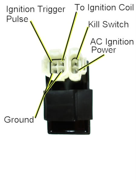
Yes, I have the Honda pinout. It shows 5 pins of the 6-pin connector are used. They are labeled IGN, SW, EXT, PC, and E. IGN and PC seem to be the two leads for the magnetic pickup and are along the left side of the diagram. SW is colored black and is in the middle along the top. EXT I think is DC power is in the upper right, and E which is green is in the lower right and I am pretty sure is ground. The manual lists ohm readings for 6 pin pairs to test.
I've had the intermittent spark problem for quite some time - several years.
By checking the connector at the harness with a continuity meter I've previously ruled out connector problems, however recently 2 wires broke off - right at the connector. I was able to reconnect one and use a jumper wire for the other. (I haven't yet tried 4 more jumpers) Anyway, for these reasons I think the wiring issues are known but not the problem. Plenty of contact cleaner has also been applied.
When just nothing else works, whacking the CDI module (which means removing the seat and the tank) with anything hard seems to get it to start and usually stay working for the rest of the day. Nothing at the connector or wiring has this effect.
...
Okay, having answered how to the best of my knowledge I have 2 separate problems in proximity, I will proclaim my ignorance of exactly what smarts goes into a CDI unit.
I understand that very similar models of ATV's called for different CDI modules. Mine is a 1984 ATC 200 ES. The ES designation is for a utility version with racks. Ones with just an S designation, no racks, but otherwise seeming the same to me, perhaps are for other fun purposes, in which speed and higher engine RPM needs would benefit from different timing?
So a mismatched CDI unit could interfere with timing?
Is it something which I could check with a timing light by catching my old CDI working and checking a substitute to see if its the same, perhaps at both idle and medium engine speed after all mechanical advance happens?
Or do the CDI's electronics do something dynamic based on engine speed or engine speed over time?
At a simple level if a CDI isn't much more than an amplifier of the low voltage magnetic pickup that switches full battery power to the coil in sync or with a fixed tiny duration delay after the magnetic pickup I am not sure why an inexpensive aftermarket unit wouldn't work provided the coils and spark plug gap are close in their electrical properties.
And that is why I've been thinking about splicing in a different connector to solve the wiring problem at the same time as trying a different CDI unit.
#4
10-19-2011, 11:55 PM
Electrical Expert
Likes High Voltage In The Tub!
Likes High Voltage In The Tub!
Join Date: Dec 2008
Location: Tracy, California, USA
Posts: 3,260
Likes: 0
Received 12 Likes
on
12 Posts
I'm going to embed my comments outside and within your post in blue...
1) Is this a picture of your Honda CDI?
2) If so, is the unused pin labeled above a ground pin? Or is it some other pin?
3) Does the 110cc CDI have five pins or four pins?
1) Is this a picture of your Honda CDI?
2) If so, is the unused pin labeled above a ground pin? Or is it some other pin?
3) Does the 110cc CDI have five pins or four pins?
Yes, I have the Honda pinout. It shows 5 pins of the 6-pin connector are used. They are labeled IGN, SW, EXT, PC, and E. IGN and PC seem to be the two leads for the magnetic pickup and are along the left side of the diagram. SW is colored black and is in the middle along the top. EXT I think is DC power is in the upper right, and E which is green is in the lower right and I am pretty sure is ground. The manual lists ohm readings for 6 pin pairs to test.
I've had the intermittent spark problem for quite some time - several years.
By checking the connector at the harness with a continuity meter I've previously ruled out connector problems, however recently 2 wires broke off - right at the connector. I was able to reconnect one and use a jumper wire for the other. (I haven't yet tried 4 more jumpers) Anyway, for these reasons I think the wiring issues are known but not the problem. Plenty of contact cleaner has also been applied.
When just nothing else works, whacking the CDI module (which means removing the seat and the tank) with anything hard seems to get it to start and usually stay working for the rest of the day. Nothing at the connector or wiring has this effect. [Hmmm... It is possible for there to be an intermittent connection inside the CDI. If wiggling wire ate the connector doesn't solve it, and whacking the CDI itself (while making sure you aren't transferring some of that energy elsewhere and fooling yourself) does solve the problem, then that does point to the CDI.]
...
Okay, having answered how to the best of my knowledge I have 2 separate problems in proximity, I will proclaim my ignorance of exactly what smarts goes into a CDI unit.
I understand that very similar models of ATV's called for different CDI modules. Mine is a 1984 ATC 200 ES. The ES designation is for a utility version with racks. Ones with just an S designation, no racks, but otherwise seeming the same to me, perhaps are for other fun purposes, in which speed and higher engine RPM needs would benefit from different timing? [I don't know anything about either model...]
So a mismatched CDI unit could interfere with timing? [Yes, but more on this below...]
Is it something which I could check with a timing light by catching my old CDI working and checking a substitute to see if its the same, perhaps at both idle and medium engine speed after all mechanical advance happens? [Yes, absolutely you could check the ignition advance timing between two CDI modules and compare. But do it over the full range from idle to high speed. If they're the same then you're good to go. Note: I don't think there is any mechanical timing advance in your quad. Again I don't know about your quad, but every chinese quad I've seen does the timing advance using the timing pickup coil in conjunction with the CDI electronics. It's much simpler than any mechanical contraption.]
Or do the CDI's electronics do something dynamic based on engine speed or engine speed over time? [The timing pickup coil works by spinning a raised block of steel on the flywheel in close fly by past a magnet with a coil of wire wrapped around it. The raised bump bends the magnetic field from the magnet back and forth at each edge of the 'bump' which generates a +/- voltage pulse pair out of the coil. This fires the CDI. This process of generating voltages from moving magnetic fields past coils or wire is called Faraday Induction (in case you want to look it up), and the voltage produced by the coil is proportional to the rate of change of magnetic field variation (i.e. engine speed). This voltage increase at higher speeds from the pickup coil is used by the CDI to advance the timing at higher engine RPM's. The circuitry necessary to do this inside the CDI is very simple if you're not too much of a perfectionist. For the perfectionists there are performance CDIs that add another level of timing advance control.]
At a simple level if a CDI isn't much more than an amplifier of the low voltage magnetic pickup that switches full battery power to the coil in sync or with a fixed tiny duration delay after the magnetic pickup I am not sure why an inexpensive aftermarket unit wouldn't work provided the coils and spark plug gap are close in their electrical properties. [This part is completely wrong. *ALL* CDIs run on moderately high voltage internally (one to several hundred volts DC). *None* run on 12 volts internally. But, there are some that are powered by 12 volts DC - but these take the 12 volts input and use a DC to DC switching power supply inside to take 12 volts and jack it up to a couple hundred volts or so. In the case of AC powered CDIs the moderately high voltage AC power input is simply rectified to make the high voltage DC internal supply. Both methods use this moderately high voltage DC internal supply to charge up a large capacitor (The "C" in the acronym "CDI). At the proper time the trigger signal dumps the charge on this capacitor onto the coil primary, which gets stepped up again by the coil to make spark.]
And that is why I've been thinking about splicing in a different connector to solve the wiring problem at the same time as trying a different CDI unit.
[It might work. But it will take some work to see. You'll need to get it sparking and verify the timing advance]
#5
10-22-2011, 07:23 PM
Join Date: Oct 2011
Posts: 8
Likes: 0
Received 0 Likes
on
0 Posts
The 3-wheeler big red has a single six-pin connector. From a manual I found that it actually only uses 5 of those 6 pins. I don't yet know any more.
The 110cc quad has a single six-pin connector as well.
The two connectors have a resemblance but the honda's has a large round connector in addition. A quick search on ebay shows similar connectors on CDI modules of similar ATV's.
[IMG]file:///C:/DOCUME%7E1/rob/LOCALS%7E1/Temp/moz-screenshot.png[/IMG]I could send an image or picture by email but I don't know how to insert anything other than text in this type of forum.
Thank you for understanding what I meant to convey by the difference between wiggling wires and whacking the CDI unit.
Thank you for the detail of what a CDI does. If only I still had access to some of the signal processing equipment I used decades ago in college perhaps I could better understand even at the black box level. So the DC input to the coil is not 12V, but actually hundreds of volts?
From what you described it sounds like the spark generation circuit anticipates the need based on the data collected by the magnetic pickup. In the case of a rapid increase or decrease in engine speed I would expect that to be hard or I guess, as you say, imperfect, or something I couldn't imagine designing [over-engineering?] without additional sensor inputs.
#6
10-23-2011, 09:46 PM
Electrical Expert
Likes High Voltage In The Tub!
Likes High Voltage In The Tub!
Join Date: Dec 2008
Location: Tracy, California, USA
Posts: 3,260
Likes: 0
Received 12 Likes
on
12 Posts
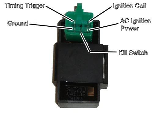
Note that there is space for a 6'th pin, but none is inserted. I was doing some reading about old Honda CDI's and apparently there are some that do have six pins? At DrATV OPERATES HERE they show a reverse indicator wire going to that sixth pin. That's got me stumped - I don't know why the CDI should know or care whether you are in reverse. Perhaps the diagram at DrATV is a mistake. All the other five wires at DrATV matched the standard wire colors and pinout above.
In any case you have only five wires. I looked back through all the text. I don't see a list of your wire colors at the CDI anywhere. What are the five wire colors? How do they connect to the pins in the 5 pin CDI above? I suspect that your CDI harness pinout is going to match the pinout above - at least as far as what I've found today in searching around.
For example, the above picture of the 5 pin CDI is actually the following text minus the asterisks. I added the asterisks to make it an invalid address so that it reverts to displaying the mistyped text instead of the picture:

It is also possible to upload your picture to the forum and let them host it. But the forum doesn't allow that to happen until you've posted like 20 times. Its to prevent spamming I suppose...
....thank you for the detail of what a cdi does. If only i still had access to some of the signal processing equipment i used decades ago in college perhaps i could better understand even at the black box level. So the dc input to the coil is not 12v, but actually hundreds of volts?....
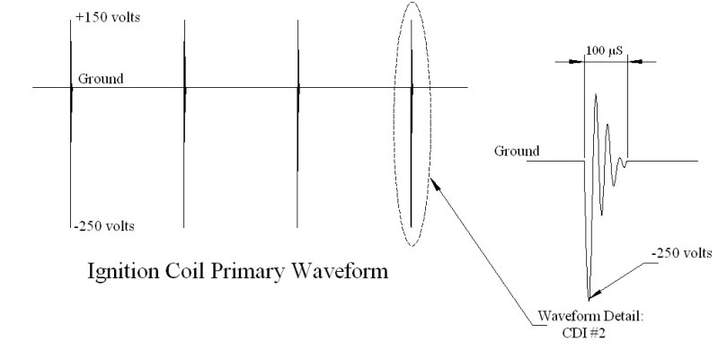
Note how the input voltages are high frequency high voltage AC pulses (ringing at 30 Kilo Hertz). There is no 12 volt anything at the ignition coil. If you applied 12 volts DC to the ignition coil it would burn up.
from what you described it sounds like the spark generation circuit anticipates the need based on the data collected by the magnetic pickup. In the case of a rapid increase or decrease in engine speed i would expect that to be hard or i guess, as you say, imperfect, or something i couldn't imagine designing [over-engineering?] without additional sensor inputs.
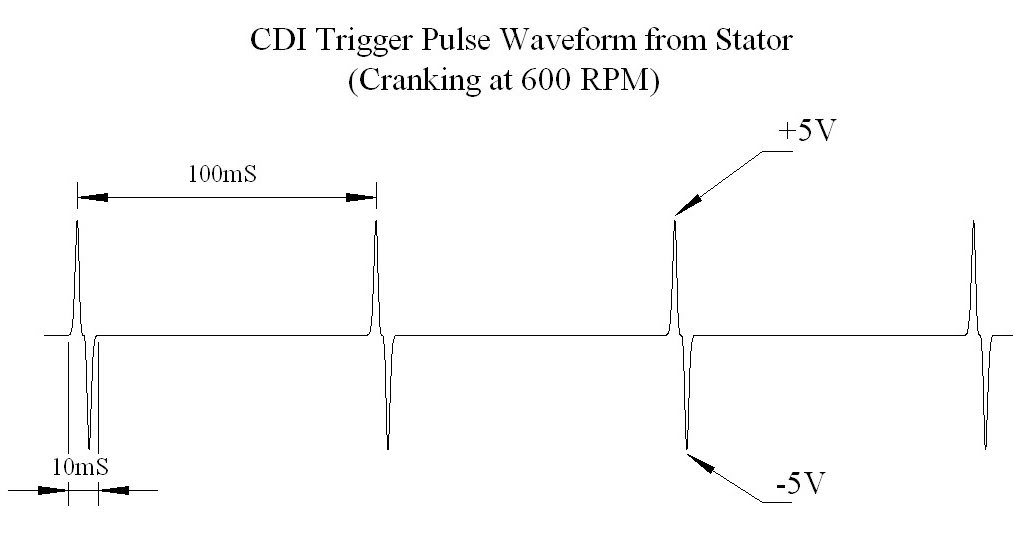
On a most CDIs the first pulse of the pair arms the CDI, the second fires it. The voltages shown are at cranking speed. But as the engine speed increases the amplitude of those pulses get bigger, and they get a little broader at the base. The CDI sets a fixed threshold that fires the CDI. At higher engine RPMs the broadening of the waveform base causes that firing threshold to be reached a little bit sooner. That advances the ignition timing.
#7
10-23-2011, 11:59 PM
Join Date: Oct 2011
Posts: 8
Likes: 0
Received 0 Likes
on
0 Posts
I see that my ATC200ES does apparently have a mechanical timing advance: *SPARK_ADVANCER SEE_DISCRIPTION (277W) Here's an uploaded image from the manual Honda CDI pinout picture by rob613photobucket - Photobucket It really does have 6 pins on its connector, just 1 isn't used according to my manual. The magnetic pickup I see does give an AC signal. Those waveforms you posted were very clear. Now if a modern 110cc mini ATV doesn't have a mechanical advance, and the CDI unit does that, probably even if I could match up the pins I would not be able to substitute. The description of the mechanical advance at DrATV is consistent with what I discovered about the subtle CDI unit differences among the different model designations of similar ATV's to mine.
Trending Topics
#8
10-24-2011, 11:12 PM
Electrical Expert
Likes High Voltage In The Tub!
Likes High Voltage In The Tub!
Join Date: Dec 2008
Location: Tracy, California, USA
Posts: 3,260
Likes: 0
Received 12 Likes
on
12 Posts
I see that my ATC200ES does apparently have a mechanical timing advance: *SPARK_ADVANCER SEE_DISCRIPTION (277W) Here's an uploaded image from the manual Honda CDI pinout picture by rob613photobucket - Photobucket It really does have 6 pins on its connector, just 1 isn't used according to my manual...
...Now if a modern 110cc mini ATV doesn't have a mechanical advance, and the CDI unit does that, probably even if I could match up the pins I would not be able to substitute. The description of the mechanical advance at DrATV is consistent with what I discovered about the subtle CDI unit differences among the different model designations of similar ATV's to mine.
On another note, I was surprised in just googling around to find numerous 200ES owners who claim that they keep their CDIs working by banging them around. One even suggests that you fix these things by throwing them on the driveway a few times and then plug them back in. This is really strange...
 It seems more chinese than Honda
  .
.
#9
04-28-2015, 07:27 PM
Join Date: Oct 2011
Posts: 8
Likes: 0
Received 0 Likes
on
0 Posts
I replaced the CDI on my 1984 ATC 200ES some time ago after the original one had the failure mode of requiring a few whacks to give spark for the day. Now the replacement on is starting to show the same problems but it will fail abruptly on a day it worked just fine.
I never tracked down enough information to retrofit a conversion to a more readily available and less expensive CDI but I just found, I think, the DrATV information:
CDI UNIT ATC'S SEE APPLICATIONS (88D)
What am I looking at here in that one's conversion image?
http://ep.yimg.com/ca/I/dratv_2269_61592271
I'm all ears for any advice.
#10
05-10-2015, 02:39 PM
Join Date: Oct 2011
Posts: 8
Likes: 0
Received 0 Likes
on
0 Posts
I picked up a new 5/6-pin CDI for a mini ATV that I didn't need, and physically it is exactly the same size as the one from the Honda big red ATC 200 ES, just the connector pins are rotated. I found that I had a connector block from an old car radio that would fit the new CDI, just no clip to keep it in place. And I used the wiring diagram posted to retrofit it. And it works great!
I tapped onto the stock wiring harness to add this new connector. And for fun I tried 2 CDI's in parallel, and that worked too.
I even tried my old old original stock CDI that often would require a whack before it would start working for the day - as opposed to the replacement stock CDI that has begun to fail in the middle of usage, and that is working for me too. A good CDI day I guess.

Thread
Thread Starter
Forum
Replies
Last Post
John Boy
Polaris Ask an Expert! In fond memory of Old Polaris Tech.
5
07-13-2015 11:16 AM
Currently Active Users Viewing This Thread: 1 (0 members and 1 guests)