110 4 stroke wiring diagram wanted
#21
 03-13-2011, 11:29 AM


Electrical Expert
Likes High Voltage In The Tub!
Likes High Voltage In The Tub!
Join Date: Dec 2008
Location: Tracy, California, USA
Posts: 3,260
Likes: 0
Received 12 Likes
on
12 Posts
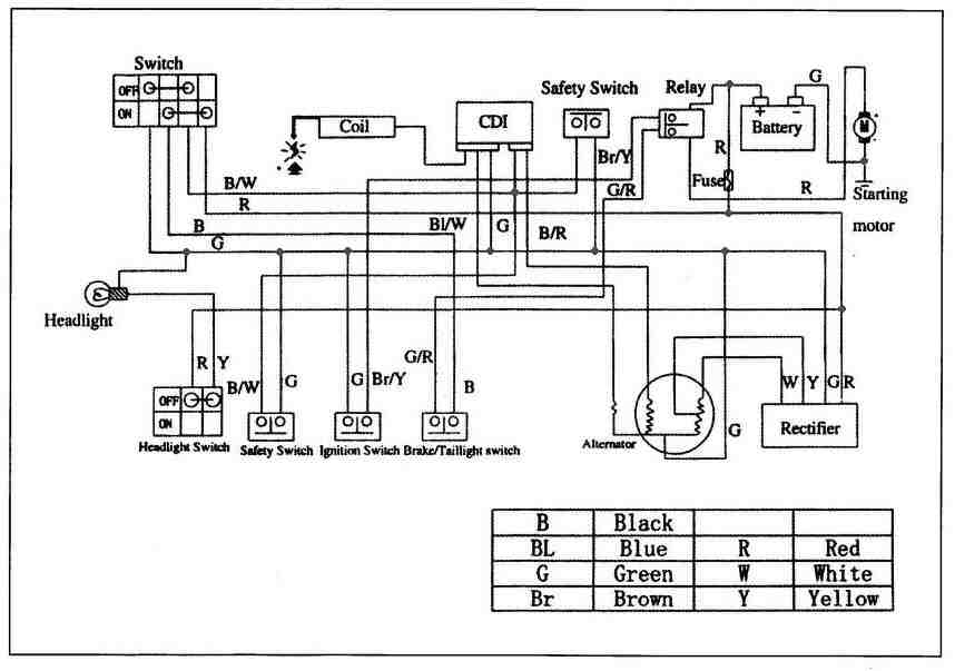
I don't have a yamoto diagram. Here is a 110cc Gio diagram. It is about as generic as they get:
Click on the picture to expand it.
Note this is for a five pin CDI (4 pin CDI wiring diagrams are different). This also does not have a remote start/stop module. Does your quad have a remote module?
Do you have spark? Take out the spark plug, wire it to the coil and hold the plug threads against the engine. Crank the starter. Do you see spark jumping across the plug electrodes?
The following users liked this post:
Kyle W (01-30-2021)
#22
12-07-2012, 07:09 PM

On my Yamoto 110, can I just unplug the remote kill box, or do I have to then splice some of the wires together?
Any help would be greatly appreciated!!
Of course, I can't find a wiring diagram specific to this little quad. I don't even know for sure if it's a 110, but it's shaft drive, Yamoto, and not all that old....black with the little red/orange flames on the front fender, and white "lightning bolt" on the gas tank...
#23
12-08-2012, 01:26 AM
Electrical Expert
Likes High Voltage In The Tub!
Likes High Voltage In The Tub!
Join Date: Dec 2008
Location: Tracy, California, USA
Posts: 3,260
Likes: 0
Received 12 Likes
on
12 Posts
On my Yamoto 110, can I just unplug the remote kill box, or do I have to then splice some of the wires together?
Any help would be greatly appreciated!!
Of course, I can't find a wiring diagram specific to this little quad. I don't even know for sure if it's a 110, but it's shaft drive, Yamoto, and not all that old....black with the little red/orange flames on the front fender, and white "lightning bolt" on the gas tank...
Any help would be greatly appreciated!!
Of course, I can't find a wiring diagram specific to this little quad. I don't even know for sure if it's a 110, but it's shaft drive, Yamoto, and not all that old....black with the little red/orange flames on the front fender, and white "lightning bolt" on the gas tank...
Below is some more generic info on remote modules that I wrote a while ago. If you need more help getting the ignition switch back to shutting off the engine come back and I will help...
Here is a diagram showing how the generic remote module is wired up for 110cc (and many other) chinese quads using the 5 pin AC powered CDI.
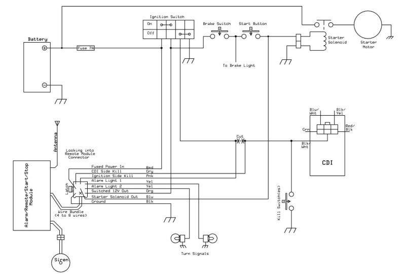
Some history: This style remote module design has been around for decades. It was used originally on motorcycles and has since been cross applied to these small chinese quads. The diagram above shows the complete set of remote start/kill/alarm module functions as it was orignally designed. They provided not only the ability to kill the engine remotely, but also allowed remote starting of the quad regardless of whether the ignition switch was on or off. And there was an alarm that drove a siren and flashed the turn signal indicators.
As these modules became more and more targeted to quads they started to drop features that aren't really all that applicable. These small quads don't have turn signals, so that feature was the first to go. The alarm is annoying, and if you think about it, the ability to remotely start up a quad even when the ignition switch is off is kind of scary. So these feature are often left out too. As these features got dropped the remote modules still used the same 9 pin wiring harness connector, but they just left the wires for the unused features off.
Here is a link for a simple remote kill switch module offered by MotorPartsMax.com (they have the best documentation of all the ones I've seen for sale so far):

Note how it only uses 4 pins on the standard connector and three wires into the module. The other pins are empty. For your quad without a remote connector you would have to wire the module directly into the wiring harness, but that would require only three wires, so it would be fairly straightforward to do.
That fourth wire from the module that does not go to the connector is the receive antenna. It just dangles.
Here is a link for a more complex module (again from MotorPartsMax.com):

Note that all the pins on the standard connector are wired up, so it supports all the functions - even flashing the turn signals when the alarm goes off - but since a typical chinese kid quad doesn't have turn signals there would just be no wire connections on the harness side of the connector. Once again this function is unused.
If you don't have a remote module connector in your wiring harness you'll have to manually wire the remote module into your harness using the above diagram. Note that to allow the remote to start up the quad with the ignition switch off you will have to cut the kill switch wire at the ignition switch and wire separate wires from the module to each side of the cut wire.
If the remote kill function is all you want then the first option is the easiest since it is only three wires to hook up: Fused 12 volt power, ground, and the kill switch connection.
One final consideration on remote modules. They are powered up all the time and drawing current from the battery. From what I've read, some draw a fair amount of current and can draw down your battery in just a couple weeks. Others are maybe not so bad. Thus when you store your quad for more than a few days it is imperative that you keep your battery on a maintenance charger (which you should be doing anyway) to keep your battery from from being damaged by sitting around partially discharged.
Some history: This style remote module design has been around for decades. It was used originally on motorcycles and has since been cross applied to these small chinese quads. The diagram above shows the complete set of remote start/kill/alarm module functions as it was orignally designed. They provided not only the ability to kill the engine remotely, but also allowed remote starting of the quad regardless of whether the ignition switch was on or off. And there was an alarm that drove a siren and flashed the turn signal indicators.
As these modules became more and more targeted to quads they started to drop features that aren't really all that applicable. These small quads don't have turn signals, so that feature was the first to go. The alarm is annoying, and if you think about it, the ability to remotely start up a quad even when the ignition switch is off is kind of scary. So these feature are often left out too. As these features got dropped the remote modules still used the same 9 pin wiring harness connector, but they just left the wires for the unused features off.
Here is a link for a simple remote kill switch module offered by MotorPartsMax.com (they have the best documentation of all the ones I've seen for sale so far):
Note how it only uses 4 pins on the standard connector and three wires into the module. The other pins are empty. For your quad without a remote connector you would have to wire the module directly into the wiring harness, but that would require only three wires, so it would be fairly straightforward to do.
That fourth wire from the module that does not go to the connector is the receive antenna. It just dangles.
Here is a link for a more complex module (again from MotorPartsMax.com):
Note that all the pins on the standard connector are wired up, so it supports all the functions - even flashing the turn signals when the alarm goes off - but since a typical chinese kid quad doesn't have turn signals there would just be no wire connections on the harness side of the connector. Once again this function is unused.
If you don't have a remote module connector in your wiring harness you'll have to manually wire the remote module into your harness using the above diagram. Note that to allow the remote to start up the quad with the ignition switch off you will have to cut the kill switch wire at the ignition switch and wire separate wires from the module to each side of the cut wire.
If the remote kill function is all you want then the first option is the easiest since it is only three wires to hook up: Fused 12 volt power, ground, and the kill switch connection.
One final consideration on remote modules. They are powered up all the time and drawing current from the battery. From what I've read, some draw a fair amount of current and can draw down your battery in just a couple weeks. Others are maybe not so bad. Thus when you store your quad for more than a few days it is imperative that you keep your battery on a maintenance charger (which you should be doing anyway) to keep your battery from from being damaged by sitting around partially discharged.
#24
12-08-2012, 12:04 PM
#25
12-20-2012, 02:35 PM

This one has the 4-pin CDI, which I bought a new one just because the old one had a bad connector.
Unhooked the remote kill and tossed it out.
The green wire at coil is grounded. The black/yellow wire to ignition coil is connected.
Replaced the left switch assy which has the headlight sw, kill sw, and starter button. For some reason the new switch had a female connector, and the chassis also had a female connector. So some butt-splicing of the old connector onto the new switch was required. However, I double-checked all the wires to make sure I connected them back up right. but it didn't have spark before I changed that switch assy, either.
Should I check the stator next? How do I check that? Is it just a resistance check through the windings? Stator has 2 yellow wires, black wire, and a blue/white wire....
Doug
#26
12-20-2012, 02:59 PM
This one has the 4-pin CDI, which I bought a new one just because the old one had a bad connector.
Unhooked the remote kill and tossed it out.
The green wire at coil is grounded. The black/yellow wire to ignition coil is connected.
Replaced the left switch assy which has the headlight sw, kill sw, and starter button. For some reason the new switch had a female connector, and the chassis also had a female connector. So some butt-splicing of the old connector onto the new switch was required. However, I double-checked all the wires to make sure I connected them back up right. but it didn't have spark before I changed that switch assy, either.
Should I check the stator next? How do I check that? Is it just a resistance check through the windings? Stator has 2 yellow wires, black wire, and a blue/white wire....
Doug
Resistance between 2 yellow stator wires is 00.8 ohms. Resistance between black and blue/white wires is 121.9 ohms.
Cranking voltage between black and blue/white wires is 131 vac.
Cranking voltage between 2 yellow wires is 7.68 vac.
Checking DC voltage from CDI box to ignition coil givea a reading of -249.XX volts. ????
Darn it! Why do these things have to be so difficult????
#27
12-21-2012, 12:29 AM
Electrical Expert
Likes High Voltage In The Tub!
Likes High Voltage In The Tub!
Join Date: Dec 2008
Location: Tracy, California, USA
Posts: 3,260
Likes: 0
Received 12 Likes
on
12 Posts
Wow, Sturgisatv, you have some mighty weird voltage measurements  . Let's discuss. My comments in blue:
. Let's discuss. My comments in blue:Resistance between 2 yellow stator wires is 00.8 ohms. [Fine, but these wires are part of the battery charging circuitry and have nothing to do with spark. So ignore these for now. We'll come back to them if necessary once you quad is running, and if your battery isn't being charged.] Resistance between black and blue/white wires is 121.9 ohms. [Where are you measuring this? At the CDI, with the CDI unplugged? ARe you measuring this at the stator? Is there a green wire (you already mentioned that green was ground on your quad) at the stator? Look carefully. Are you sure that your "black" wire is not "black with a red stripe"? Measure the resistance of each of these wires (black/??? and blue/white) to engine ground. What values do you measure?]
Cranking voltage between black and blue/white wires is 131 vac. [Yikes !!!. You said you had a four pin *DC* powered CDI. DC powered CDIs run off 12 volts DC. Inside the CDI a switch mode power supply make the moderately high voltage supply to run the ignition system. But this should not appear anywhere outside the CDI except for precisely timed triggered voltage spikes to the ignition coil. This makes no sense. Are *absolutely sure* that you need a four pin DC powered CDI? Are you *absolutely sure* that you should instead have a common 5 pin AC powered CDI?
DC powered CDIs don't have 131 volts AC, or -241 volts DC anywhere.
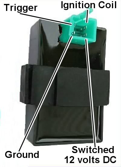
Consider the following pictures, and follow along below:
and
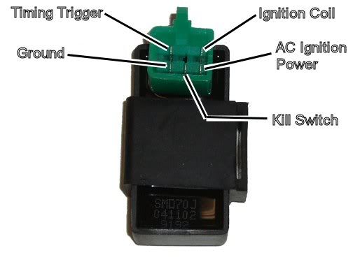
Unplug the CDI. Measure the following on the CDI connector:
1) Turn on the ignition switch. Measure the DC voltage on the AC Ignition Power Pin (or the DC power pin - the two pins a re the same on 4 and 5 pin CDIs) to the ground pin. Do you measure 12 volts DC? If so you need a DC powered (4 pin) CDI.
2) If not, then crank the starter motor with all kill switches in the "run" position. Measure the same pin again on an AC scale (200 volts) with respect to the ground pin. What do you measure? If you get large AC voltage you need a 5 pin (AC powered) CDI.]
Cranking voltage between 2 yellow wires is 7.68 vac.
Checking DC voltage from CDI box to ignition coil givea a reading of -249.XX volts. ????
Darn it! Why do these things have to be so difficult????
Cranking voltage between black and blue/white wires is 131 vac. [Yikes
!!!. You said you had a four pin *DC* powered CDI. DC powered CDIs run off 12 volts DC. Inside the CDI a switch mode power supply make the moderately high voltage supply to run the ignition system. But this should not appear anywhere outside the CDI except for precisely timed triggered voltage spikes to the ignition coil. This makes no sense. Are *absolutely sure* that you need a four pin DC powered CDI? Are you *absolutely sure* that you should instead have a common 5 pin AC powered CDI?DC powered CDIs don't have 131 volts AC, or -241 volts DC anywhere.
Consider the following pictures, and follow along below:
and
Unplug the CDI. Measure the following on the CDI connector:
1) Turn on the ignition switch. Measure the DC voltage on the AC Ignition Power Pin (or the DC power pin - the two pins a re the same on 4 and 5 pin CDIs) to the ground pin. Do you measure 12 volts DC? If so you need a DC powered (4 pin) CDI.
2) If not, then crank the starter motor with all kill switches in the "run" position. Measure the same pin again on an AC scale (200 volts) with respect to the ground pin. What do you measure? If you get large AC voltage you need a 5 pin (AC powered) CDI.]
Cranking voltage between 2 yellow wires is 7.68 vac.
Checking DC voltage from CDI box to ignition coil givea a reading of -249.XX volts. ????
Darn it! Why do these things have to be so difficult????
#28
12-21-2012, 08:40 AM
#29
12-21-2012, 03:47 PM
Ok, Lynn, I get 12.23 volts between the AC Power pin and the ground pin (green wire) on this thing. Previous voltage readings were directly from the stator connector. Now I am reading this from the CDI connector.
#30
12-22-2012, 12:09 AM
Electrical Expert
Likes High Voltage In The Tub!
Likes High Voltage In The Tub!
Join Date: Dec 2008
Location: Tracy, California, USA
Posts: 3,260
Likes: 0
Received 12 Likes
on
12 Posts
So what about 131 volts, or -249 volts? This simply cannot be then. If your CDI was AC powered it would be powered from moderately high voltage AC coming from the stator - which would appear in many places. Typical voltages would be from 45 to 80 volts though, not 131 volts. But I haven't seen every quad brand in the universe, so maybe 131 volts isn't out of this world.
But since your quad is really DC powered I suspect measurement error. When you measure these enormous voltages what scale are you using on the meter? Could it be that you are measuring millivolts instead of volts - like you are on a 2 volt scale? 131 millivolts is the same as 0.131 volts. Thats a difference of 1000 times compared to 131 volts. Imagine if you went to the bank to check your balance in you checking account and they told you it was 131 thousand dollars, when in fact it was only 131 dollars. That would be a life altering realization
.Here is a generic procedure fro testing a DC powered 4 pin CDI:
To troubleshoot no spark problems on a 4 pin DC powered CDI it makes sense to start in the middle (the CDI), measure as much as we can and branch out from there. For the CDI to do its thing it needs power and ground, and a trigger pulse.
1) Unplug the CDI. Turn the ignition switch on. Set all kill switches to the the "run" position. Use
a meter to measure the DC voltage on the pin labeled "AC ignition power" in the wiring harness to the ground wire on the 20 volt DC scale. You should read battery voltage (12 volts). What do you measure?
2) Leave the CDI unplugged. Use a meter to measure the resistance of the "Ignition Trigger Pulse" pin in the wiring harness to the ground wire on the 2K ohm scale. You should read approximately 150 ohms. What do you measure?
3) Set your meter down to the lowest scale you have for measuring AC volts. 2 volts would be ideal, but some meters don't go that low. In that case use the lowest scale you have. While cranking the engine, measure the voltage on the Ignition Trigger Pulse pin in the wiring harness to the ground pin. You should measure 0.2 to 0.5 volts AC. What do you measure?
4) Now plug the CDI back in. Measure the AC voltage on the Ignition Coil pin to the ground pin using the 200 volt scale. If you have to, use a sewing pin to poke through the wire insulation and then put the meter probe on the sewing pin. But don't hold your fingers on the connection during the next test - there may be high voltage here when the engine is turning. With the ignition on and all kill switches set to the "run" position, crank the starter motor. You should see voltages bouncing around at random values and the meter captures all or part of a spark event. What do you see?