Stator/Megneto Problem on a 150cc
#11
 06-28-2011, 12:09 AM


Electrical Expert
Likes High Voltage In The Tub!
Likes High Voltage In The Tub!
Join Date: Dec 2008
Location: Tracy, California, USA
Posts: 3,260
Likes: 0
Received 12 Likes
on
12 Posts
I've been pouring over various quad wire diagrams, and thinking a lot. Having the starter motor disabled when the CDI is unplugged is really weird. I need some more info....
On your two CDI's there are two ground pins:
1) Use an ohmmeter to see if both your CDI's have the two ground pins hooked together inside the CDI (should measure zero ohms, or shorted).
2) Next measure the two ground pins in the wiring harness. Are they shorted (zero ohms)?
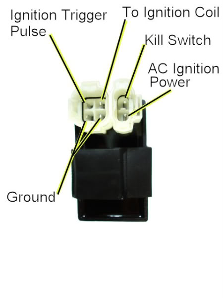
3) Repeat the test that you did earlier shown in quoted text below... But this time measure between the Ignition Trigger Pulse pin and both ground pins. You measured infinite ohms before. But do you get 150 ohms or so when measuring between the Ignition Trigger Pulse pin and *either* ground pin?
On most CDIs the two ground pins are tied together inside the CDI. On some quads the ground return of the stator trigger pick up coil is tied into the main ground through the CDI - i.e. the CDI shorts the two grounds together. This still shouldn't keep the starter from turning with the CDI unplugged, but maybe there is a missing ground somewhere...
One more thing to try: Unplug the CDI and use a pair of long nose pliers to manually short the two ground pins together in the CDI wiring harness connector. Turn on the ignition, set the parking brake, then attempt to crank the starter motor. With the CDI unplugged and the grounds shorted together, does the quad starter turn?
On your two CDI's there are two ground pins:
1) Use an ohmmeter to see if both your CDI's have the two ground pins hooked together inside the CDI (should measure zero ohms, or shorted).
2) Next measure the two ground pins in the wiring harness. Are they shorted (zero ohms)?
3) Repeat the test that you did earlier shown in quoted text below... But this time measure between the Ignition Trigger Pulse pin and both ground pins. You measured infinite ohms before. But do you get 150 ohms or so when measuring between the Ignition Trigger Pulse pin and *either* ground pin?
Leave the CDI unplugged. Use a meter to measure the resistance of the "Ignition Trigger Pulse" pin in the wiring harness to the ground wire on the 2K ohm scale. You should read approximately 150 ohms. What do you measure?
One more thing to try: Unplug the CDI and use a pair of long nose pliers to manually short the two ground pins together in the CDI wiring harness connector. Turn on the ignition, set the parking brake, then attempt to crank the starter motor. With the CDI unplugged and the grounds shorted together, does the quad starter turn?
#12
06-29-2011, 12:19 AM
Electrical Expert
Likes High Voltage In The Tub!
Likes High Voltage In The Tub!
Join Date: Dec 2008
Location: Tracy, California, USA
Posts: 3,260
Likes: 0
Received 12 Likes
on
12 Posts
I'm still thinking about this and am still some what perplexed...
But there is another tact to take in addition to the CDI tests and the trigger wire being open tests:
Pull out the CDI so that the starter doesn't turn over, then let's start using a meter to find out why. Turn on the ignition and set the parking brake.
1) Is the brake light on? (it should be)
2) What is the DC voltage on both side of the 2 small wires on the starter solenoid with respect to ground?
3) Press the start button and hold it in... Use the meter to measure the following (while holding the start button in:
3A) What is the DC voltage on both of the small wires on the starter solenoid?
3B) What is the DC voltage on the battery itself? Measure the positive terminal to the minus terminal while holding the starter button in...
Mysteries are easily solved once enough accurate information is acquired. This is a mystery, and more info will shed light. It's quite possible that all your symptoms are related, and approaching the problem from multiple angles will provide information that will help get to the solution.
Complex problems always seem much more easy in retrospect ...
#13
06-29-2011, 09:03 AM

Join Date: May 2011
Posts: 10
Likes: 0
Received 0 Likes
on
0 Posts
2) Next measure the two ground pins in the wiring harness. Are they shorted (zero ohms)?
3) Repeat the test that you did earlier shown in quoted text below... But this time measure between the Ignition Trigger Pulse pin and both ground pins. You measured infinite ohms before. But do you get 150 ohms or so when measuring between the Ignition Trigger Pulse pin and *either* ground pin?
With the CDI unplugged and the grounds shorted together, does the quad starter turn?
If the group of four wires on the CDI (trigger pulse, coil, and two grounds) are removed and the other two are left in, the startor motor will still turn over.
1) Is the brake light on? (it should be)
2) What is the DC voltage on both side of the 2 small wires on the starter solenoid with respect to ground?
3) Press the start button and hold it in... Use the meter to measure the following (while holding the start button in:
3A) What is the DC voltage on both of the small wires on the starter solenoid?
3B) What is the DC voltage on the battery itself? Measure the positive terminal to the minus terminal while holding the starter button in...
2. I read no volts
3. No volts
A. No volts
B. It did not drop any from 12.35VDC
#14
06-29-2011, 11:33 PM
Electrical Expert
Likes High Voltage In The Tub!
Likes High Voltage In The Tub!
Join Date: Dec 2008
Location: Tracy, California, USA
Posts: 3,260
Likes: 0
Received 12 Likes
on
12 Posts
My comments in blue...
Your comments in red...
Quote:
Originally Posted by LynnEdwards
1) Use an ohmmeter to see if both your CDI's have the two ground pins hooked together inside the CDI (should measure zero ohms, or shorted).
The Smaller CDI reads zero ohms, the larger one reads infinite.
This is a problem. Both grounds in your wiring harness need to be hooked together. Only your small CDI (which may require AC power) is going to accomplish this. Your other (probably DC CDI) will not. This first thing I would do is wire these two wires together so that they are connected no matter what CDI is plugged in. All grounds need to be tied together. You measured that they aren't tied in the wiring harness, and they aren't in both CDI's. It's OK to have the ground wires tied together both in the wiring and the CDI.
Quote:
2) Next measure the two ground pins in the wiring harness. Are they shorted (zero ohms)?
No
Again, they need to get shorted together somewhere. If not in the CDI then you can do it manually in the wiring harness.
Quote:
3) Repeat the test that you did earlier shown in quoted text below... But this time measure between the Ignition Trigger Pulse pin and both ground pins. You measured infinite ohms before. But do you get 150 ohms or so when measuring between the Ignition Trigger Pulse pin and *either* ground pin?
I measured 136.5 Ohms with the ground pin not directly below it.
This is progress. Before the trigger pulse pin was open. The ignition won't work this way. No trigger, no spark... Connect the two ground wires at the CDI together in the wiring harness and this confounding variable is out of the way.
Quote:
With the CDI unplugged and the grounds shorted together, does the quad starter turn?
no it does not
If the group of four wires on the CDI (trigger pulse, coil, and two grounds) are removed and the other two are left in, the startor motor will still turn over.
This really, really weird. What you are saying is (if I'm understanding you):
You connect just the two wires to the CDI:
1) 12 volts (CDI power) and the
2) Kill switch pin (which should be open [i.e. not connected to anything when attempting to start the quad])
to one CDI the quad starter motor works. But if you connect the other CDI the quad starter motor does not work.
This makes no logical sense. Simply connecting battery power (12 volts) to the CDI has nothing to do with whether the starter will turn or not, and the kill switch wire has nothing to do with the starter turning also.
This is so weird that I must ask you to please verify this again. Take extra care, and to make sure to approach the tests with a skeptical eye. Before we go embarking down this bizarre and unknown path let's make sure our information foundation is solid at the outset. Otherwise we will be visiting the proverbial garden path.
Quote:
1) Is the brake light on? (it should be)
2) What is the DC voltage on both side of the 2 small wires on the starter solenoid with respect to ground?
3) Press the start button and hold it in... Use the meter to measure the following (while holding the start button in:
3A) What is the DC voltage on both of the small wires on the starter solenoid?
3B) What is the DC voltage on the battery itself? Measure the positive terminal to the minus terminal while holding the starter button in...
1. No, but would a miswiring in the main switch be to blame for that, because two wires are not connected in the switch.
2. I read no volts
3. No volts
A. No volts
B. It did not drop any from 12.35VDC
1, 2, and 3A are weird in the same vein as the last. For the starter motor to turn we need to get 12 volts on one side of the starter motor solenoid actuating coil (the small wires), and ground on the other. But you measure no 12 volts period.
So if you hook up the CDI that does engage the starter, and measure the voltages at the starter solenoid small wires while cranking the starter, do you see 12 volts on on side and ground at the other?
If you disconnect the kill switch wire at the CDI and repeat, does the starter cease to crank?
Your comments in red...
Quote:
Originally Posted by LynnEdwards
1) Use an ohmmeter to see if both your CDI's have the two ground pins hooked together inside the CDI (should measure zero ohms, or shorted).
The Smaller CDI reads zero ohms, the larger one reads infinite.
This is a problem. Both grounds in your wiring harness need to be hooked together. Only your small CDI (which may require AC power) is going to accomplish this. Your other (probably DC CDI) will not. This first thing I would do is wire these two wires together so that they are connected no matter what CDI is plugged in. All grounds need to be tied together. You measured that they aren't tied in the wiring harness, and they aren't in both CDI's. It's OK to have the ground wires tied together both in the wiring and the CDI.
Quote:
2) Next measure the two ground pins in the wiring harness. Are they shorted (zero ohms)?
No
Again, they need to get shorted together somewhere. If not in the CDI then you can do it manually in the wiring harness.
Quote:
3) Repeat the test that you did earlier shown in quoted text below... But this time measure between the Ignition Trigger Pulse pin and both ground pins. You measured infinite ohms before. But do you get 150 ohms or so when measuring between the Ignition Trigger Pulse pin and *either* ground pin?
I measured 136.5 Ohms with the ground pin not directly below it.
This is progress. Before the trigger pulse pin was open. The ignition won't work this way. No trigger, no spark... Connect the two ground wires at the CDI together in the wiring harness and this confounding variable is out of the way.
Quote:
With the CDI unplugged and the grounds shorted together, does the quad starter turn?
no it does not
If the group of four wires on the CDI (trigger pulse, coil, and two grounds) are removed and the other two are left in, the startor motor will still turn over.
This really, really weird. What you are saying is (if I'm understanding you):
You connect just the two wires to the CDI:
1) 12 volts (CDI power) and the
2) Kill switch pin (which should be open [i.e. not connected to anything when attempting to start the quad])
to one CDI the quad starter motor works. But if you connect the other CDI the quad starter motor does not work.
This makes no logical sense. Simply connecting battery power (12 volts) to the CDI has nothing to do with whether the starter will turn or not, and the kill switch wire has nothing to do with the starter turning also.
This is so weird that I must ask you to please verify this again. Take extra care, and to make sure to approach the tests with a skeptical eye. Before we go embarking down this bizarre and unknown path let's make sure our information foundation is solid at the outset. Otherwise we will be visiting the proverbial garden path
.Quote:
1) Is the brake light on? (it should be)
2) What is the DC voltage on both side of the 2 small wires on the starter solenoid with respect to ground?
3) Press the start button and hold it in... Use the meter to measure the following (while holding the start button in:
3A) What is the DC voltage on both of the small wires on the starter solenoid?
3B) What is the DC voltage on the battery itself? Measure the positive terminal to the minus terminal while holding the starter button in...
1. No, but would a miswiring in the main switch be to blame for that, because two wires are not connected in the switch.
2. I read no volts
3. No volts
A. No volts
B. It did not drop any from 12.35VDC
1, 2, and 3A are weird in the same vein as the last. For the starter motor to turn we need to get 12 volts on one side of the starter motor solenoid actuating coil (the small wires), and ground on the other. But you measure no 12 volts period.
So if you hook up the CDI that does engage the starter, and measure the voltages at the starter solenoid small wires while cranking the starter, do you see 12 volts on on side and ground at the other?
If you disconnect the kill switch wire at the CDI and repeat, does the starter cease to crank?
#15
11-23-2011, 03:55 PM
Join Date: May 2011
Posts: 10
Likes: 0
Received 0 Likes
on
0 Posts
So, its been awhile since I last touched this project, I got extremely busy and had other priorities. BUT! I am getting started on this again, and Ive already made progress. What I have done since the last round of tests, is I bought a new wiring harness because I wasnt satisfied with the spaghetti mess that was previously there. And then I went through the wiring harness and eliminated all unessesary items( to me anyways; headlights, brakelights, fuel gauge, all handle bar switches and keys and then disconnected all kill switches from the cdi). I am left with the bare minimum to start and hopefully run the atv.
Doing that fixed the problem of the CDI controling whether or not the starter turns over. Now that I know I have a D.C. CDI, I wired it accordingly (A.C. Power Pin getting 12V, instead of an A.C. lead from the stator). And when I attempted to see if I got a spark, I did! but it was very weak and would not start the atv. So I am buying a new DC CDI, an ignition coil and cable, and sparkplug, all to make sure I have brand new working parts. I was also considering buying a new Magneto Stator Plate, just to ensure that is new aswell, but my question is, is a 6 or 8 pole magneto better for my atv? or does that not matter?
Doing that fixed the problem of the CDI controling whether or not the starter turns over. Now that I know I have a D.C. CDI, I wired it accordingly (A.C. Power Pin getting 12V, instead of an A.C. lead from the stator). And when I attempted to see if I got a spark, I did! but it was very weak and would not start the atv. So I am buying a new DC CDI, an ignition coil and cable, and sparkplug, all to make sure I have brand new working parts. I was also considering buying a new Magneto Stator Plate, just to ensure that is new aswell, but my question is, is a 6 or 8 pole magneto better for my atv? or does that not matter?
#16
11-24-2011, 02:43 PM
Electrical Expert
Likes High Voltage In The Tub!
Likes High Voltage In The Tub!
Join Date: Dec 2008
Location: Tracy, California, USA
Posts: 3,260
Likes: 0
Received 12 Likes
on
12 Posts
Eight pole stators put out more battery charging current than six pole stators. If given the choice go for eight pole. The problem with six pole stators is that you really don't have enough power to run a pair of headights and keep the battery charged at the same time.
But remember that the stator and flywheel must match. A six pole flywheel has six magnets embedded in it. An eight pole stator has eight magnets in it. The magnets in the flywheel must line up simulateously with the stator poles as it spins. If you put a six pole stator in an eight magnet flywheel your battery charging system will not work at all.
But remember that the stator and flywheel must match. A six pole flywheel has six magnets embedded in it. An eight pole stator has eight magnets in it. The magnets in the flywheel must line up simulateously with the stator poles as it spins. If you put a six pole stator in an eight magnet flywheel your battery charging system will not work at all.
#17
12-16-2011, 07:37 PM
Join Date: May 2011
Posts: 10
Likes: 0
Received 0 Likes
on
0 Posts
Thanks for your help so far, I am pleased to say that I got it started and idleing (after replacing the carb, cdi, ignition coil, and spark plug... didnt replace the actual stator..yet) i can run it in forward and reverse, BUT! as i start to accelerate faster than walking speed, it sputters and bogs as in its going to shut down, but it wont, it will just go the same speed and pop and jerk around..So i think it might be one of the following.
The trigger coil of the stator isnt functioning right, so that would mean my timing is off not allowing me to accelerate...
Or
The Lighting coil isnt right because, i connected my automatic choke(spliced) directly to the yellow lighting coil wire before the regulator module.
And also, this 6pole stator should be producing enough current to keep the quad running after i remove the battery (since its a DC cdi), right? because it will stall after i remove it. Is there a way to check the regulator?
Last edited by sktbrd2; 12-16-2011 at 07:44 PM. Reason: More information
#18
12-17-2011, 12:00 AM
Electrical Expert
Likes High Voltage In The Tub!
Likes High Voltage In The Tub!
Join Date: Dec 2008
Location: Tracy, California, USA
Posts: 3,260
Likes: 0
Received 12 Likes
on
12 Posts
My comments in blue...
Thanks for your help so far, I am pleased to say that I got it started and idleing (after replacing the carb, cdi, ignition coil, and spark plug... didnt replace the actual stator..yet) i can run it in forward and reverse, [This is progress...] BUT! as i start to accelerate faster than walking speed, it sputters and bogs as in its going to shut down, but it wont, it will just go the same speed and pop and jerk around..So i think it might be one of the following. [I think it is sounding more like carburetion issues....]
The trigger coil of the stator isnt functioning right, so that would mean my timing is off not allowing me to accelerate... [Almost certainly not.... The trigger signal is fixed (not adjustable) and is an "all or nothing" signal. It either musters up enough voltage to fire the CDI, or it doesn't. Your get spark, or you don't. Also, (and this is a key point), the voltage from the trigger coil is proportional to engine speed. The faster the engine spins the more voltage produced. So if you have any trouble with the trigger signal the symptom will be a total lack of spark at cranking speeds. Cranking speed is 600 RPM, idle speed is roughly three times that at 1700 RPMs. So if the quad starts and idles you have about three times over the signal level required to fire the CDI - which remember is an "all or nothing" signal]
Or
The Lighting coil isnt right because, i connected my automatic choke(spliced) directly to the yellow lighting coil wire before the regulator module. [Ok, but does your quad run fine when cold? When cold the choke is on and everything is as it should. If your lighting coil isn't up to snuff then you would run fine when cold, but as the quad warms up you would be too rich. The idle would be high, and vary (if your quad is the same as mine with a stuck choke). But it would run and accelerate, albeit with some black smoke out the exhaust]
And also, this 6pole stator should be producing enough current to keep the quad running after i remove the battery (since its a DC cdi), right? because it will stall after i remove it. Is there a way to check the regulator?[Yes, absolutely as long as the headlights are off. If your quad dies when the battery is removed your charging system is not working]
#20
12-17-2011, 10:18 PM
Electrical Expert
Likes High Voltage In The Tub!
Likes High Voltage In The Tub!
Join Date: Dec 2008
Location: Tracy, California, USA
Posts: 3,260
Likes: 0
Received 12 Likes
on
12 Posts
Your regulator could be bad, or any of the wiring to/from the stator/regulator/battery.
Unplug the regulator and measure the two stator output voltages at idle. Usually this is a yellow and a white wire at the regulator connector. Measure the "AC" volts on each of these wires to engine ground at idle. What voltages do you measure?
Also measure the AC voltage between the yellow and white wire at the regulator connector. What do you measure?