Stator/Megneto Problem on a 150cc
#1
 06-10-2011, 07:16 PM


Join Date: May 2011
Posts: 10
Likes: 0
Received 0 Likes
on
0 Posts
Ok so I have an alphasports LG-150 with a no spark problem... I bought a manual with wiring diagrams (Diagrams, not schematics as i would have liked) and ive already checked my ignition coil, solenoid, starter switch, kill switch, reverse indicator, brake sensor, battery and fuse, so ive narrowed it down to the magneto/stator... The manual shows that i have four wires coming from what it calls the generator ( im assuming magneto/stator because the colors match up). BUT, i have five wires coming from the actual coil; yellow, green, and white all go to the voltage rectifier/regulator; a blue/yellow wire goes right to the CDI.. But i have a black/red wire just hanging out.. Im pretty sure thats important, but my diagram doesnt even have a color code for a black with red stripe wire on it at all. So where does this mystery wire go, and what does it do? or is this the wrong magneto coil thing in my atv?
#2
06-10-2011, 11:33 PM

Electrical Expert
Likes High Voltage In The Tub!
Likes High Voltage In The Tub!
Join Date: Dec 2008
Location: Tracy, California, USA
Posts: 3,260
Likes: 0
Received 12 Likes
on
12 Posts
How exactly did you test the kill switch? How did you test the ignition coil?
... The manual shows that i have four wires coming from what it calls the generator ( im assuming magneto/stator because the colors match up). BUT, i have five wires coming from the actual coil; yellow, green, and white all go to the voltage rectifier/regulator; a blue/yellow wire goes right to the CDI.. But i have a black/red wire just hanging out.. Im pretty sure thats important, but my diagram doesnt even have a color code for a black with red stripe wire on it at all. So where does this mystery wire go, and what does it do? or is this the wrong magneto coil thing in my atv?
The black red wire from the stator is the AC power wire that goes to the CDI in an AC powered ignition system. On quads with 12 volt DC powered ignition systems most do not have this wire. Yet there are transition quads that still have the AC ignition power coil in the stator even though the CDI uses DC power. I suspect your quad ignition is DC powered. If this is true then this wire would just dangle unconnected.
For your no spark problem I would first find out for sure if your CDI is DC powered or AC powered. You cannot tell by looking at the CDI - they often look the same. Check out this link for some good info on how to measure this:
http://forums.atvconnection.com/chin...se-stator.html
Then use a meter to measure all the inputs to the CDI with the CDI disconnected:
1) Power (power - be it AC or DC)
2) Trigger signal
3) Kill switch(es)
4) Ground
After that measure the CDI output as best as we can using a meter.
I can guide though this process, but where to start? Please explain the measurements you've done so far eliminating the kill switch(es), ignition coil, and interconnect wiring. Or we can start at the beginning if that is easier
 .
.
#3
06-11-2011, 01:22 AM
Join Date: May 2011
Posts: 10
Likes: 0
Received 0 Likes
on
0 Posts
Thank you for the quick reply, yes i am usuing the starter motor to turn the engine.. So I checked the kill switch with my meter and its wires coming from the switch, making sure when it should and shouldnt be an open or closed circut.. I tested the ignition coil like it told me in the manual, to read its resistance across the two spade connectors, which was .3ohms, then from the green lead to the end of the plug wire which was 3 ohms, so according to the book, its fine. The CDI is D.C. because the manual wants a peak reading in D.C. of 130-230 V going to the ignition coil but i havent done any tests on the CDI's output nor imput yet because i was focused on my "generator"'s loose wire. But that black/red wire reads A.C. so it would be best to stub and secure that wire?
#4
06-11-2011, 04:21 PM
Electrical Expert
Likes High Voltage In The Tub!
Likes High Voltage In The Tub!
Join Date: Dec 2008
Location: Tracy, California, USA
Posts: 3,260
Likes: 0
Received 12 Likes
on
12 Posts
Excellent.
OK, though it is better to check kill switches from the CDI wiring harness plug (with the CDI disconnected). That way you are checking the switch and all associated wiring as well.
Ditto for checking the ignition coil primary coil. One of the spade lugs on the coil goes to the CDI, the other goes to ground. By measuring the coil from the CDI plug your also checking the wiring at the same time.
You can only partially check and ignition coil with a meter. A shorted turn inside will keep the coil form working at all even though the reistances are in spec. Also high voltage flashover to ground cannot be detected. So what we do is measure everything in the ignition system as best we can, and if something simple doesn't pop out make the best educated guess that we can.
The output of the CDI is always AC, not DC, irrespective of what your manual says. The CDI output drives the ignition coil which is essentially a transformer. Transformers only work with AC voltage. If there was any DC component it would be shorted out by 0.3 ohms resistance of the primary.
Whether a CDI is DC or AC specifies what powers it. An AC CDI runs off a moderately high voltage (80-300 volts or so) AC winding inside the stator. A DC powered CDI runs off 12 volts DC and high has an internal convertor supply to convert that up to the couple hundred volts needed to run the rest of the CDI.
So you still need to determine if your CDI is AC or DC. As I recall from your post a couple months back you got this quad in pieces with the CDI coming with it loose. Am I remembering correctly? What I'm wondering is if this quad is someones basket case where they put a new DC CDI wiring harness on an AC CDI quad.
If your quad is wired up for a DC CDI then you can just tape up that wire and ignore it.
Below is a procedure for determining whether you CDI is AC powered or DC powered. It is block copied from another post so some of what is in there is redundant. Step 2 is guaranteed to fail since your AC power from the stator is disconnected. If you don't have a DC powered CDI then we may need to hook this up. If you do have a DC powered CDI then look at the next block for trouble shooting the no spark problem.
.. So I checked the kill switch with my meter and its wires coming from the switch, making sure when it should and shouldnt be an open or closed circut.. I tested the ignition coil like it told me in the manual, to read its resistance across the two spade connectors, which was .3ohms, then from the green lead to the end of the plug wire which was 3 ohms, so according to the book, its fine.....
Ditto for checking the ignition coil primary coil. One of the spade lugs on the coil goes to the CDI, the other goes to ground. By measuring the coil from the CDI plug your also checking the wiring at the same time.
You can only partially check and ignition coil with a meter. A shorted turn inside will keep the coil form working at all even though the reistances are in spec. Also high voltage flashover to ground cannot be detected. So what we do is measure everything in the ignition system as best we can, and if something simple doesn't pop out make the best educated guess that we can.
Whether a CDI is DC or AC specifies what powers it. An AC CDI runs off a moderately high voltage (80-300 volts or so) AC winding inside the stator. A DC powered CDI runs off 12 volts DC and high has an internal convertor supply to convert that up to the couple hundred volts needed to run the rest of the CDI.
So you still need to determine if your CDI is AC or DC. As I recall from your post a couple months back you got this quad in pieces with the CDI coming with it loose. Am I remembering correctly? What I'm wondering is if this quad is someones basket case where they put a new DC CDI wiring harness on an AC CDI quad.
Below is a procedure for determining whether you CDI is AC powered or DC powered. It is block copied from another post so some of what is in there is redundant. Step 2 is guaranteed to fail since your AC power from the stator is disconnected. If you don't have a DC powered CDI then we may need to hook this up. If you do have a DC powered CDI then look at the next block for trouble shooting the no spark problem.
The 2 plug 6 wire CDIs come in two different designs. One is powered off 12 volts DC, and the other is powered off a moderately high voltage AC which comes from the stator. Unfortunately there is no reliable way to tell the difference between the two by just looking at them. To be sure you need to use a meter to find out which you have:
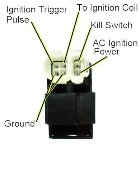
1) Unplug the CDI, and turn on the ignition. Do not crank the starter motor. Use a meter to meausure the *DC* voltage on the pin labeled "AC ignition power" in the wiring harness to the ground pin in the same connector. If you measure 12 volts DC then you have a DC powered CDI.
2) If you don't measure 12 volts DC on the ignition power pin, then switch the meter over to measure AC volts on the 200 volt scale. While cranking the starter motor, measure the AC voltage on the "AC Ignition Power" pin to the the Ground pin. You should see 40 to 80 volts AC. If you measure AC voltage when the starter is turning then you have an AC powered CDI.
Using a meter is the only 100% reliable way to figure out if your CDI is AC or DC powered. But there are some clues you can use that are usually (but not always) correct:
A) DC CDIs tend to be a little larger than their AC powered counterpart. This is because the DC powered CDI needs a bunch more circuitry to convert the 12 volts DC to the moderately high voltage supply that CDIs must have.
B) Most (but not all) DC powered quad ignition systems do not use the kill switch input pin. The CDI connector pin usually has no wire tied to it. AC powered quad ignition systems usually do use the kill switch input pin.
To troubleshoot no spark problems on a 6 pin DC powered CDI it makes sense to start in the middle (the CDI), measure as much as we can and branch out from there. For the CDI to do its thing it needs power, a trigger pulse, and it must not be inhibited via the kill switch input pin.
1) Unplug the CDI. Turn the ignition switch on. Set all kill switches the the "run" position. In the wiring harness, look to see if you have a wire on the kill switch pin. If you do, measure the resistance of the kill switch pin to the ground pin on the 20K ohm scale. It should read infinite ohms same as when the meter leads are hanging free and not touching anything). It should not read zero ohms (shorted).
2) Leave the CDI unplugged, and the ignition switch in the "on" position. Use a meter to measure the DC voltage on the pin labeled "AC ignition power" in the wiring harness to the ground wire on the 2K ohm scale. You should read battery voltage (12 volts). What do you measure?
3) Leave the CDI unplugged. Use a meter to measure the resistance of the "Ignition Trigger Pulse" pin in the wiring harness to the ground wire on the 2K ohm scale. You should read approximately 150 ohms. What do you measure?
4) Set your meter down to the lowest scale you have for measuring AC volts. 2 volts would be ideal, but some meters don't go that low. In that case use the lowest scale you have. While cranking the engine, measure the voltage on the Ignition Trigger Pulse pin in the wiring harness to the ground pin. You should measure 0.2 to 0.5 volts AC. What do you measure?
5) Now plug the CDI back in. Measure the AC voltage on the Ignition Coil pin to the ground pin using the 200 volt scale. If you have to, use a sewing pin to poke through the wire insulation and then put the meter probe on the sewing pin. But don't hold your fingers on the connection during the next test - there may be high voltage here when the engine is turning. With the ignition on and all kill switches set to the "run" position, crank the starter motor. You should see voltages bouncing around at random values and the meter captures all or part of a spark event. What do you see?
#5
06-16-2011, 09:22 PM
Join Date: May 2011
Posts: 10
Likes: 0
Received 0 Likes
on
0 Posts
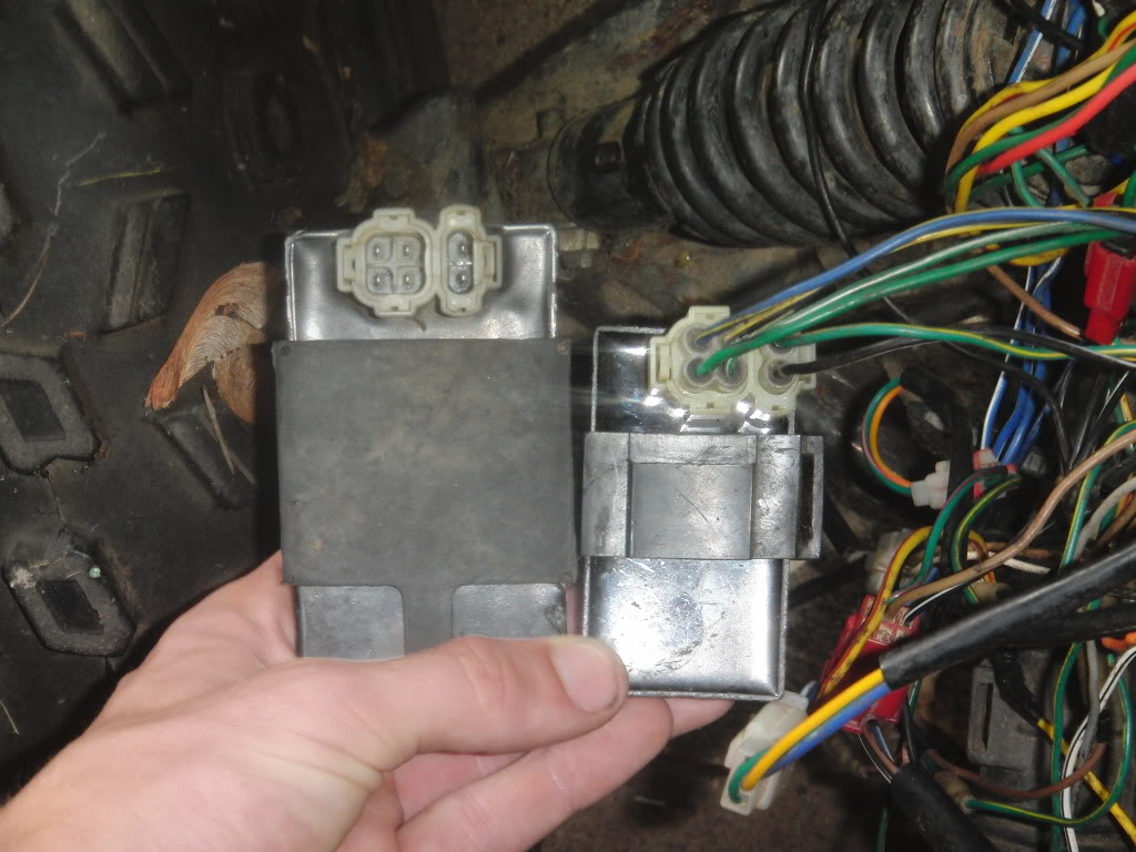
Your right, this was someones basket case, i previously had a thread about the bare wires for a CDI, that I found out was incorrect and those were for the main switch. The guy I bought this from told me those wires were for another CDI (me being a ATV novice, i assumed incorrectly), well i got those wires taken care of.. But he said he replaced the cdi and also the magneto, but i think he changed the cdi from either an A/C to a DC or vice versa, Because i have two boxes, a larger one that does nothing went connected, and a smaller one that will turn over my starter. In your last post it says that DC cdi's tend to be bigger, and the larger CDI doesnt work when i attempt to turn it over, so does that mean i have an AC one, or a faulty DC one?
#6
06-16-2011, 10:26 PM
Electrical Expert
Likes High Voltage In The Tub!
Likes High Voltage In The Tub!
Join Date: Dec 2008
Location: Tracy, California, USA
Posts: 3,260
Likes: 0
Received 12 Likes
on
12 Posts
... Because i have two boxes, a larger one that does nothing went connected, and a smaller one that will turn over my starter. In your last post it says that DC cdi's tend to be bigger, and the larger CDI doesnt work when i attempt to turn it over, so does that mean i have an AC one, or a faulty DC one?
Hmmm... I think you are going about this all wrong. I really think you should be measuring your wiring harness at the CDI connector (CDI unplugged) to see whether your wiring harness is powering the CDI with DC. Then check the trigger voltage, kill switch connections, etc - all from the CDI connector. The procedures are in the last post. If you find trouble here it doesn't matter if you have a truck load full of CDI's - it isn't going to work. So in my humble opinion it is premature to focus in on CDI module itself (or the stator red/blk wire, or any other component yet). First you want to gather overall data for the whole ignition system, so that you're seeing the big picture. Then we can narrow in on suspicious areas within the ignition system
.
#7
06-26-2011, 04:52 PM
Join Date: May 2011
Posts: 10
Likes: 0
Received 0 Likes
on
0 Posts
I'm not understanding this... What does "a smaller one that will turn over my starter" mean? A CDI has nothing to do with starter motors, which is leaving me puzzled...
A) DC CDIs tend to be a little larger than their AC powered counterpart. This is because the DC powered CDI needs a bunch more circuitry to convert the 12 volts DC to the moderately high voltage supply that CDIs must have.
But either way, i attempted those tests described in your post.
1) Unplug the CDI, and turn on the ignition. Do not crank the starter motor. Use a meter to meausure the *DC* voltage on the pin labeled "AC ignition power" in the wiring harness to the ground pin in the same connector. If you measure 12 volts DC then you have a DC powered CDI.
1) Unplug the CDI. Turn the ignition switch on. Set all kill switches the the "run" position. In the wiring harness, look to see if you have a wire on the kill switch pin. If you do, measure the resistance of the kill switch pin to the ground pin on the 20K ohm scale. It should read infinite ohms same as when the meter leads are hanging free and not touching anything). It should not read zero ohms (shorted).
3) Leave the CDI unplugged. Use a meter to measure the resistance of the "Ignition Trigger Pulse" pin in the wiring harness to the ground wire on the 2K ohm scale. You should read approximately 150 ohms. What do you measure?
4) Set your meter down to the lowest scale you have for measuring AC volts. 2 volts would be ideal, but some meters don't go that low. In that case use the lowest scale you have. While cranking the engine, measure the voltage on the Ignition Trigger Pulse pin in the wiring harness to the ground pin. You should measure 0.2 to 0.5 volts AC. What do you measure?
5) Now plug the CDI back in. Measure the AC voltage on the Ignition Coil pin to the ground pin using the 200 volt scale. If you have to, use a sewing pin to poke through the wire insulation and then put the meter probe on the sewing pin. But don't hold your fingers on the connection during the next test - there may be high voltage here when the engine is turning. With the ignition on and all kill switches set to the "run" position, crank the starter motor. You should see voltages bouncing around at random values and the meter captures all or part of a spark event. What do you see?
So would it be wrong of me to say that I have a DC CDI, and that the tests show something is wrong with the ignition coil? Well thats assuming the test results are accurate with my meter.
Trending Topics
#8
06-27-2011, 01:27 AM
Electrical Expert
Likes High Voltage In The Tub!
Likes High Voltage In The Tub!
Join Date: Dec 2008
Location: Tracy, California, USA
Posts: 3,260
Likes: 0
Received 12 Likes
on
12 Posts
My comments embedded in blue:
What i meant by that was, I was given two CDI's of different sizes, the larger one when connected and the ignition button pressed, will not turn over or crank my engine. But the smaller one that is connected shown in the picture, will crank/ turn over the engine. In your post it mentioned that D.C CDI's are larger than their AC counterpart.
OK, I understand what you are saying, yet I don't think you are understanding me:
It shouldn't matter whether your CDI is powered off DC, AC, dilithium crystals, atomic power, or even psychic energy. None of this has anything to do with whether you starter motor turns or not. The CDI is not involved here. After all, you can unplug the CDI and the starter motor still turns, right? Yet you say that if you plug in the larger CDI the starter doesn't turn? This is very puzzling. It makes no sense...
But either way, i attempted those tests described in your post.
I measured 12VDC
Definitely a DC powered CDI is required for your quad
I measured infinite ohms
Fine
I did NOT measure any resistance..
Uh-Oh... What does this statement mean? Does "not measure any resistance" mean you measured zero resistance or infinite resistance? That distinction is important...
Either way it is wrong and need to be verified, and once verified looked into further...
I dont know how I got this, but it measured like 18VAC?
Doesn't sound right to me... Let's get the trigger resistance reading normal first (like 150 ohms or so), Then let's revisit this...
I got low values like 4 and 5 VAC
This doesn't sound right either. Again let's get the trigger resistance reading normal first (like 150 ohms or so), Then revisit this...
So would it be wrong of me to say that I have a DC CDI, and that the tests show something is wrong with the ignition coil? Well thats assuming the test results are accurate with my meter.
I think you measurements so far show that you have a DC powered CDI, and your CDI timing trigger input connection is measuring wrong and needs to be verified, and if necessary looked at closer
#9
06-27-2011, 10:19 AM
Join Date: May 2011
Posts: 10
Likes: 0
Received 0 Likes
on
0 Posts
None of this has anything to do with whether you starter motor turns or not. The CDI is not involved here. After all, you can unplug the CDI and the starter motor still turns, right?
Uh-Oh... What does this statement mean? Does "not measure any resistance" mean you measured zero resistance or infinite resistance? That distinction is important...
It reads the same when the meters hookups are just hanging there. So thats infinite resistance?
#10
06-27-2011, 10:38 PM
Electrical Expert
Likes High Voltage In The Tub!
Likes High Voltage In The Tub!
Join Date: Dec 2008
Location: Tracy, California, USA
Posts: 3,260
Likes: 0
Received 12 Likes
on
12 Posts
This was not an answer I expected... 
I'm really puzzled. This should not happen. Let me think about this some and I will come back after dinner...
Yes, that is infinite resistance.
I'm really puzzled. This should not happen. Let me think about this some and I will come back after dinner...
Yes, that is infinite resistance.