When you click on links to various merchants on this site and make a purchase, this can result in this site earning a commission. Affiliate programs and affiliations include, but are not limited to, the eBay Partner Network.
I'm trying to sort out some wiring connections that I found disconnected when I tore this one down for the head gasket and fuel pump stuff. I have the wiring diagram for this model, but it doesn't seem to include the wiring for the speedo. So, here's what I have and what I'm trying to sort out. Here's the 2 Speedo connectors as labeled and below is what I'm trying to sort out.
Speedo connector (6-pin)
Pin A - Red/Wht (power with key on) - for backlighting
Pin B - Brown - common ground
Pin C - Black - it is connected - ??
Pin D - Ylw/Red (constant 12 vdc key on or off)
Pin E - Brn/Wht - it is connected - ??
Pin F - Light Green - it is connected - ??
3 Pin Plug
Pin A - Red - it is connected - ??
Pin B - White - it is connected - ??
Pin C - Black - it is connected - ??
#1) Pin C of the 6-pin connector is the Black wire and it's connected to the terminal board, however the Black wire has a White wire spliced to it with a female spade connector and not connected to anything. It looks like a factory splice job.
#2) Pin B of the 6-pin connector is the Brown wire and it's connected to the terminal board, however the Brown wire has a Red/White wire spliced to it with a female spade connector and not connected to anything. It looks like a factory splice job also.
#3) White wire coming from throttle for the ETC is not connected to anything. Has a female spade terminal. Diagram shows it should be connected to the LR-83 Hub Safety Switch, but I can't seem to find the Safety Switch in question.
#4) Speedo backlighting is inop. I'm guessing a bulb since power and ground are good, but looks like I have to disassemble the speedo to get to it though. (I'm not too concerned on that really).
There were several other disconnected wires but with the diagrams and cleaning up the terminal board to see terminal labels, I got them all sorted out.
Is there a separate diagram for the speedo circuitry so I can learn what wire does what and where these wires should be connected?
Speedo connector (6-pin)
Pin A - Red/Wht (power with key on) - for backlighting..... Yes
Pin B - Brown - common ground Yes
Pin C - Black - ?? hub safety switch(module)
Pin D - Ylw/Red (constant 12 vdc key on or off) voltage regulator(rpm)
Pin E - Brn/Wht - ?? ground wire for awd coil
Pin F - Light Green - ?? hub safety switch
3 Pin Plug
Pin A - Red
Pin B - White This plug/wiring goes to the wheel speed sensor
Pin C - Black
And no,manuals don't show any speedo circuitry... Hook up what you know is right then process of elimination on the rest of it..The schematic should help,just trace the wires from the speedo connector on it.. Next time get an atv that a Rottweiler hasn't taken his frustration out on ..
Last edited by old polaris tech; 01-31-2016 at 02:45 PM.
Reason: black and green wires
Thanks OPT. I seem to be a glutton for punishment getting these things. Just hate to see what could be a great ATV/golf cart/etc going to waste and being neglected.
Like I said, a glutton for punishment.
When I meant not showing the Speedo circuitry, I meant not showing the speedo 2 plugs at all, not the speedo internals. Sorry for the confusion.
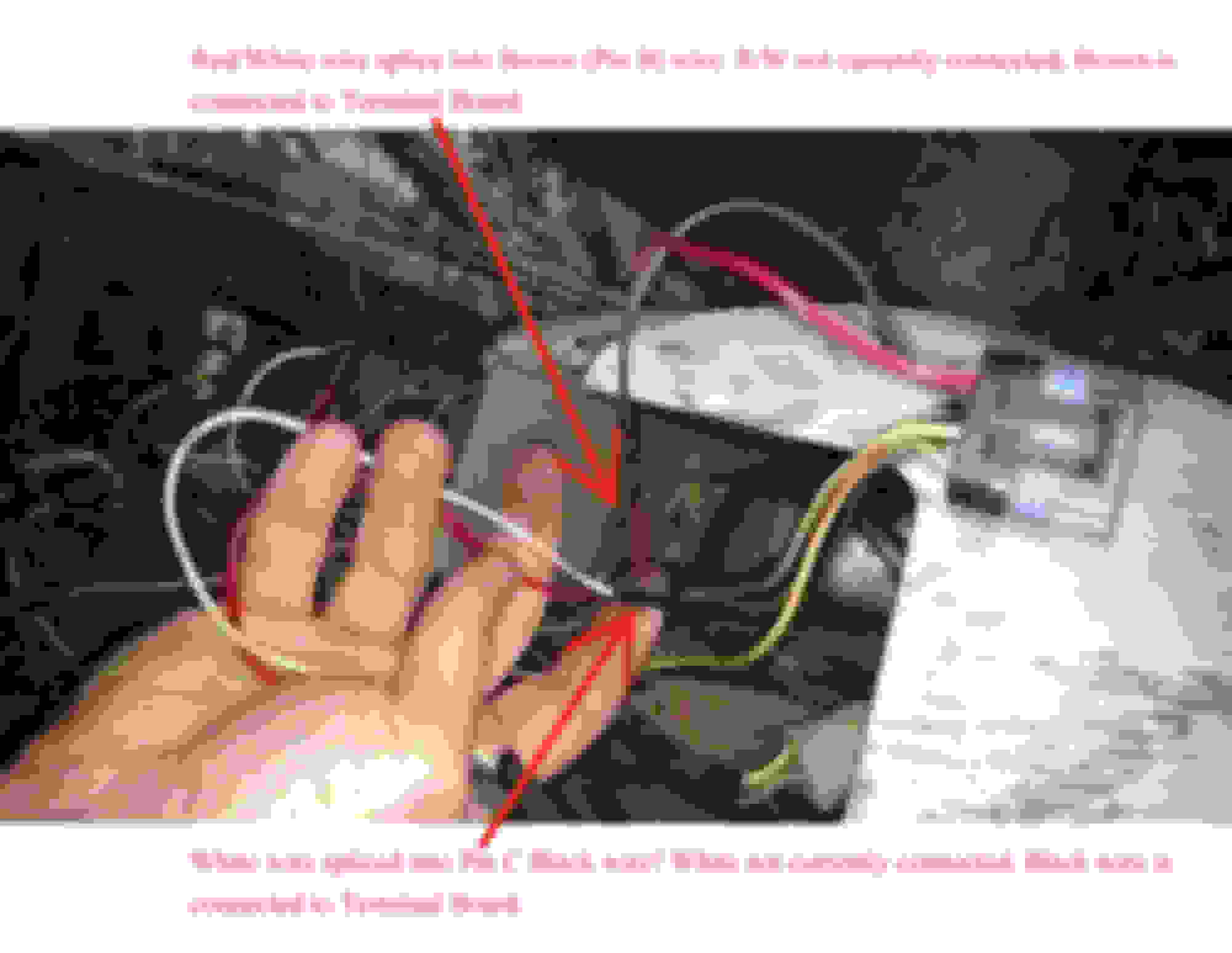
So, from what you responded and giving it another look over, I think I found the HUB Safety Module (in plain site under the terminal board it seems....). So I connected the white wire to the terminal board which matched it up with the white wire for the Module (diagram doesn't exactly show that). So, #3 is solved I hope. Now, back to those spliced wires not connected coming from Pin B and C of the 6-pin. See the pic attached. The Black (pin C) and Brown (pin B) are already connected to their respective terminal board spots. What would the pictured wires connect to then? Again, looking at the splice points, they seem factory looking as all the others I found on the harness. Hoping a pic will help. These are my last 2 unknowns now.
Doesn't look right on the red/white tied into a brown(ground) as the red/white is a power wire that's hot when ignition is on.But it might be the SPARE red/white that's used for auxiliary equipment that most models have. Again the white and black go down to the hall effect sensor mounted on the right front brake caliper. Look down in that area to see if you can trace these down.
My thoughts exactly on the Red/White. Everything I've ever touched in the past that was a power wire. Why would it be spliced to a ground. I'm going to just clip that off and forget I ever saw it.....lol. Hell, even if it were for an accessory port, it would mess someone up being spliced to the ground side.
Now, as for the white wire spliced into the black (of the 6-pin connector). I pulled the right front tire and traced that sensor all the way up to the 3-pin plug on the speedo. That's not the white wire I'm speaking of. Again, sorry for any confusion.
On the terminal board there's only 2 White terminals (for the aforementioned Hub Safety Module) and those are occupied. Right now the speedo doesn't seem to work (didn't work when I got it either). So I may just let that slide. I can't expect to get everything 100% sometimes. I think it's time to put this thing back together and go play in some mud!
Once again, thanks for all your expertise. Not showing the speedo connectors on any diagrams made this a guessing game unfortunately.
Too bad it wasn't a later model(2005) as the manuals do have a dedicated speedo troubleshooting section with pin wiring and trouble shooting checks. The two manuals I have: 96-98 All Models and 1996-2003 Sportsman 400-500 don't have this. These concentrate mainly on ignition and charging and on the schematic barely show the speedo connectors. Later manuals probably wouldn't help you a lot on this and wouldn't be accurate as the speedos are different,more complicated and wiring is different.
Well, at least they learned from their mistakes eventually...... Sounds like you have the manuals I have also. Heck, I may even have gotten from you in the past, I can't remember where I found the pdf's. Dayum.....I just got a sticker shock when looking at a new Speedo (99-02 were the same electronic type).....$400!!!, even on eBay....That's nuts. Maybe I'll get lucky and find someone parting out an ATV sooner or later.
 01-31-2016, 01:10 PM


") . Sounds like you have the manuals I have also. Heck, I may even have gotten from you in the past, I can't remember where I found the pdf's. Dayum.....I just got a sticker shock when looking at a new Speedo (99-02 were the same electronic type).....$400!!!, even on eBay....That's nuts. Maybe I'll get lucky and find someone parting out an ATV sooner or later.
. Sounds like you have the manuals I have also. Heck, I may even have gotten from you in the past, I can't remember where I found the pdf's. Dayum.....I just got a sticker shock when looking at a new Speedo (99-02 were the same electronic type).....$400!!!, even on eBay....That's nuts. Maybe I'll get lucky and find someone parting out an ATV sooner or later.
