
What wiring harness will fit my hanma 110cc atv?
 Aug 16, 2011 | 11:14 PM
#1

Thread Starter
|
Weekend Warrior
Joined: Aug 2011
Posts: 3
Likes: 0
From: pa
Hi yall i have a hanma 110cc atv but heres the twist.... the guy i bought it off of swiched the engine with a 125cc auto with reverse engine. the old wiring harness doesnt fit the 125cc engine. it has two wires comming outa the engine. i can rebuild an engine but not rewire the friggin thin  . does anyone know of a harness that will fit? maybe you guys have one i could buy off of you????
i need help thanks-Brandon
I can post any pics you guys need to help me find the harness...
. does anyone know of a harness that will fit? maybe you guys have one i could buy off of you???? i need help
thanks-BrandonI can post any pics you guys need to help me find the harness...
Aug 16, 2011 | 11:59 PM
#2

Electrical Expert
Likes High Voltage In The Tub!
Likes High Voltage In The Tub!
Joined: Dec 2008
Posts: 3,260
Likes: 14
From: Tracy, California, USA
I wouldn't think there is anyone who would make a commercially available wiring harness for that vast untapped market where the engine has been changed from Hanma 110cc to some sort of 125cc engine ") . Maybe I'm wrong...
. Maybe I'm wrong...
Cynicism aside, now that the engine has been changed, have you ever seen it run? Did the guy you bought it off of ever get it to run? Or are you just buying a basket case that somebody else gave up on (and probably let it sit for two or three years besides)?
OK. Now my cynisim is *really* aside .
.
You say you have two wires coming out of the engine. That is not nearly enough. Please check again. How many wires, and what colors are they?
You say the wiring harness doesn't match. But by how much? Does anything fit?
In it's current state, does anything work? Can you turn on the headlights? Crank the starter? Do you have spark? Brake lights work?
Is your CDI AC powered or DC powered? Is your new engine set up for AC powered CDI's or DC powered CDI's? Do you need help in figuring this out?
Do you have a meter? Are you willing to use it to fix your problems?
All of this is solvable, but from your initial description it sounds like a big job. I'm up to it, if you are ....
. Maybe I'm wrong...Cynicism aside, now that the engine has been changed, have you ever seen it run? Did the guy you bought it off of ever get it to run? Or are you just buying a basket case that somebody else gave up on (and probably let it sit for two or three years besides)?
OK. Now my cynisim is *really* aside
.You say you have two wires coming out of the engine. That is not nearly enough. Please check again. How many wires, and what colors are they?
You say the wiring harness doesn't match. But by how much? Does anything fit?
In it's current state, does anything work? Can you turn on the headlights? Crank the starter? Do you have spark? Brake lights work?
Is your CDI AC powered or DC powered? Is your new engine set up for AC powered CDI's or DC powered CDI's? Do you need help in figuring this out?
Do you have a meter? Are you willing to use it to fix your problems?
All of this is solvable, but from your initial description it sounds like a big job. I'm up to it, if you are ...
.
Aug 17, 2011 | 05:04 PM
#3
Thread Starter
|
Weekend Warrior
Joined: Aug 2011
Posts: 3
Likes: 0
From: pa
Thank you very much! the guy claims it has ran b4 and just needed a new clutch. when i bought it it had the engine out of the frame so i couldnt test it to see what worked and what didnt. i will take pics a few hours from now and show u what all wires match up. theres one wire that does and it connects to the harness but the other wire doesnt but it fits the cdi. 
Aug 18, 2011 | 10:57 PM
#4
Thread Starter
|
Weekend Warrior
Joined: Aug 2011
Posts: 3
Likes: 0
From: pa
well i tested it out for the first time todayyy and guess what it has spark! yessss then i put a lil gas in the cylinder and it fired right up! all i need is a new fuel line and i need to buy a clutch. thanks for your help
 Sep 21, 2011 | 12:39 AM
#7
Electrical Expert
Likes High Voltage In The Tub!
Likes High Voltage In The Tub!
Joined: Dec 2008
Posts: 3,260
Likes: 14
From: Tracy, California, USA
.
Is this a picture of your CDI?
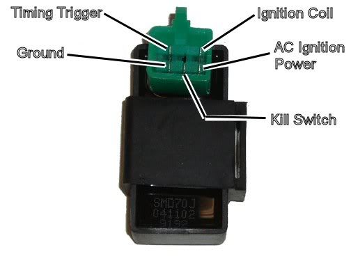
Assuming the answer is yes, the first thing to do is eliminate all kill switches and kill switch wiring:
Method 1) Unplug the CDI and remove the kill switch pin in the CDI connector on the wiring harness. The pin is held in with a spring tab on the pin itself. You'll have to probe into the connector and push this tab in order to extract the pin. Plug the CDI back in (kill switch wire dangling) and see if you have spark.
Method 2) Unplug the CDI. Turn on the ignition switch and set all kill switches to the run position. Use a meter to measure resistance in of the kill switch pin in the wiring harness connector to engine/frame ground. If the reistance is infinite on the 100K ohm scale then your kill switches/kill switch wiring are OK. If you measure zero ohms then you have a kill switch/wiring issue.
The other inputs your CDI needs to make spark are AC Ignition Power, and the Trigger signal. Do the following:
1) Unplug the CDI. In the wiring connector measure the resistance of the AC Ignition Power pin to the Ground pin. You should see 400 ohms or so. What do you measure?
2) Measure the resistance of the Timing/trigger pin to the ground pin. You should measure 150 ohms or so. What do you measure?
3) Leave the CDI unplugged. Set your meter to measure AC volts on the 100 volt scale. Measure the voltage on the AC Ignition Power pin to the ground pin while cranking the engine. You should see 40 to 80 volts AC while the engine is cranking. What do you measure?
4) Set your meter to measure AC volts on the lowest scale you have. Ideally this would be 2 volts but many meters don't go down this low. In that case use the lowest scale you have. Measure the voltage on the Timing Trigger pin to the Ground pin while cranking the engine. You should 0.2 t0 0.4 volts AC. What do you measure?
Now for measuring the output side of the CDI:
A) Leave the CDI unplugged. In the CDI wiring connector measure the resistance of the Ignition Coil pin to the ground pin. You should measure less than 1 ohm (but not zero ohms). What do you measure?
B) Plug the CDI back in. Set your meter to measure AC volts on the 20 volt scale. Set all kill switches to the run position. Crank the engine while measuring the voltage on the Igntition Coil pin to ground. Poke through the insulation of the wire if you can't probe the connector.
Caution: There should be moderately high voltage spikes on this wire. Make sure your fingers are not part of the circuitry. Don't touch the probe lead tips while doing this test.
What you should see is a lot of random numbers with lots of zero values as well. This is because the meter may catch all or part of the spark event voltage, with a lot of nothing in between. Describe what you see.
Note: Using a meter to measure this point produces highly variable results depending on the meter. What you really need is an oscilloscope, but most always a meter is all that is available. We have to do the best we can with what's available. Describe the meter results as accurately as you can - there is information there to chew on....
Trending Topics
Sep 21, 2011 | 11:22 PM
#9
Electrical Expert
Likes High Voltage In The Tub!
Likes High Voltage In The Tub!
Joined: Dec 2008
Posts: 3,260
Likes: 14
From: Tracy, California, USA
A four pin CDI is a quite different situation from a five pin CDI. Here is a generic procedure for troubleshooing a 4 pin CDI:
To troubleshoot no spark problems on a 4 pin DC powered CDI it makes sense to start in the middle
(the CDI), measure as much as we can and branch out from there. For the CDI to do its thing it needs
power and ground, and a trigger pulse.
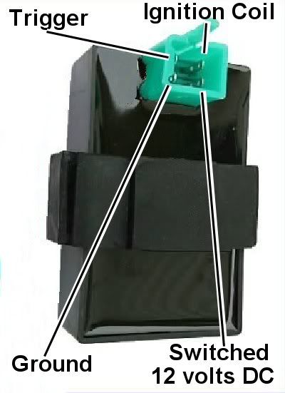
1) Unplug the CDI. Turn the ignition switch on. Set all kill switches to the the "run" position. Use a meter to measure the DC voltage on the pin labeled "AC ignition power" in the wiring harness to the ground wire You should read battery voltage (12 volts). What do you measure?
2) Leave the CDI unplugged. Use a meter to measure the resistance of the "Ignition Trigger Pulse" pin in
the wiring harness to the ground wire on the 2K ohm scale. You should read approximately 150 ohms. What
do you measure?
3) Set your meter down to the lowest scale you have for measuring AC volts. 2 volts would be ideal, but
some meters don't go that low. In that case use the lowest scale you have. While cranking the engine,
measure the voltage on the Ignition Trigger Pulse pin in the wiring harness to the ground pin. You should
measure 0.2 to 0.5 volts AC. What do you measure?
4) Now plug the CDI back in. Measure the AC voltage on the Ignition Coil pin to the ground pin using the
200 volt scale. If you have to, use a sewing pin to poke through the wire insulation and then put the
meter probe on the sewing pin. But don't hold your fingers on the connection during the next test - there
may be high voltage here when the engine is turning. With the ignition on and all kill switches set to
the "run" position, crank the starter motor. You should see voltages bouncing around at random values and
the meter captures all or part of a spark event. What do you see?
(the CDI), measure as much as we can and branch out from there. For the CDI to do its thing it needs
power and ground, and a trigger pulse.
1) Unplug the CDI. Turn the ignition switch on. Set all kill switches to the the "run" position. Use a meter to measure the DC voltage on the pin labeled "AC ignition power" in the wiring harness to the ground wire You should read battery voltage (12 volts). What do you measure?
2) Leave the CDI unplugged. Use a meter to measure the resistance of the "Ignition Trigger Pulse" pin in
the wiring harness to the ground wire on the 2K ohm scale. You should read approximately 150 ohms. What
do you measure?
3) Set your meter down to the lowest scale you have for measuring AC volts. 2 volts would be ideal, but
some meters don't go that low. In that case use the lowest scale you have. While cranking the engine,
measure the voltage on the Ignition Trigger Pulse pin in the wiring harness to the ground pin. You should
measure 0.2 to 0.5 volts AC. What do you measure?
4) Now plug the CDI back in. Measure the AC voltage on the Ignition Coil pin to the ground pin using the
200 volt scale. If you have to, use a sewing pin to poke through the wire insulation and then put the
meter probe on the sewing pin. But don't hold your fingers on the connection during the next test - there
may be high voltage here when the engine is turning. With the ignition on and all kill switches set to
the "run" position, crank the starter motor. You should see voltages bouncing around at random values and
the meter captures all or part of a spark event. What do you see?

Thread
Thread Starter
Forum
Replies
Last Post
bradco
Polaris Ask an Expert! In fond memory of Old Polaris Tech.
9
Aug 21, 2015 08:11 PM
400H0
Polaris Ask an Expert! In fond memory of Old Polaris Tech.
10
Aug 20, 2015 07:34 PM
tank10rnk
General Chat
2
Aug 10, 2015 08:19 PM
Currently Active Users Viewing This Thread: 1 (0 members and 1 guests)