
2007 KinRoad ATV Quad 200CC Hooking up Reverse/Neutral switch wires
 Jun 25, 2012 | 11:09 PM
#1

Thread Starter
|
Weekend Warrior
Joined: Jun 2012
Posts: 12
Likes: 0
Well I finally figured out many of my problems with my 2007 KinRoad 200cc not getting fire... It turned out that there were "MANY" shorts and loose connections in my Wiring Harness. After cutting out 4 different shorts, Re-soldering 7 chinese splice joints ( They Really Suck ) I decided to just build a "NEW" Wiring harness out of 14 gauge wire and upgraded my battery cables to 6 gauge, and since I work in the Aircraft field, I installed Molex aircraft connectors on ALL of my connections.  Lets just say that this wire harness will out last the Quad. LOL!! I do have one question, Since my Quad was in pieces when I got it, the Reverse/Neutral lights have never been hooked up nor marked..NOR do they match up with any other wires on the old wire harness ( ERRR!! ) and I wanted to get these hooked up. I found the 2 wires coming out of the back of the engine from the Reverse/Neutral switch so I have those marked and also the ones on my new harness. There is also this plastic connector( looks like a ground block) that 2 wires plug into ( 1 being from the Reverse/Neutral wire harness. ) Are the 2 wires coming out of the back of the engine or the Reverse/Neutral switch considered to be an open ground until you put it in Reverse/Neutral???? Trying to figure this out so that I know how to hook this up. None of this was hooked up when I got it and none of the wire colors match up. Also my LED Reverse/Neutral lights both have 2 wires coming out of each one ( Im assuming 1 positive/1 negative?? ) None of the wire colors on my OLD Harness match up well so I corrected that on my new harness. I test fired my New Harness tonight and it worked GREAT!! Engine... seems to run better and started easier. My system is a DC volt system. This is all I have left on my new Harness. Also, what does the 2 wires coming out of the clutch lever do???
Thanks, Larry
Lets just say that this wire harness will out last the Quad. LOL!! I do have one question, Since my Quad was in pieces when I got it, the Reverse/Neutral lights have never been hooked up nor marked..NOR do they match up with any other wires on the old wire harness ( ERRR!! ) and I wanted to get these hooked up. I found the 2 wires coming out of the back of the engine from the Reverse/Neutral switch so I have those marked and also the ones on my new harness. There is also this plastic connector( looks like a ground block) that 2 wires plug into ( 1 being from the Reverse/Neutral wire harness. ) Are the 2 wires coming out of the back of the engine or the Reverse/Neutral switch considered to be an open ground until you put it in Reverse/Neutral???? Trying to figure this out so that I know how to hook this up. None of this was hooked up when I got it and none of the wire colors match up. Also my LED Reverse/Neutral lights both have 2 wires coming out of each one ( Im assuming 1 positive/1 negative?? ) None of the wire colors on my OLD Harness match up well so I corrected that on my new harness. I test fired my New Harness tonight and it worked GREAT!! Engine... seems to run better and started easier. My system is a DC volt system. This is all I have left on my new Harness. Also, what does the 2 wires coming out of the clutch lever do???Thanks, Larry
Jun 26, 2012 | 09:11 AM
#2
Thread Starter
|
Weekend Warrior
Joined: Jun 2012
Posts: 12
Likes: 0
Update!! My Aircraft Avionics guys here at work figured out that the (wire block) is actually a Diode, prob for the Neutral safety switch on my bike, that explains one of my wires coming from Neutral switch, my other must be for the Reverse/Neutral LED lights, starting to figure some of this out
Jun 26, 2012 | 06:15 PM
#4
Thread Starter
|
Weekend Warrior
Joined: Jun 2012
Posts: 12
Likes: 0

Ok, this is the wiring harness coming out of my Neutral/Reverse switch. The person that had this before me cut 4 of these wires and taped them back out of the way (ERRRR!) and not sure which ones work the Reverse/Neutral LED lights.
I hope this pic will help find some answers to this.
Jun 26, 2012 | 11:10 PM
#6

Electrical Expert
Likes High Voltage In The Tub!
Likes High Voltage In The Tub!
Joined: Dec 2008
Posts: 3,260
Likes: 14
From: Tracy, California, USA
Larry,
Look at the diagram below. This is how the starter interlock is typically wired up where the safety interlock is the clutch and/or neutral switch instead of using the brake switch.
The delay in responding is because I had to make this diagram from a mix of mostly unreadable diagrams to diagrams that are riddled with errors. Here it is:
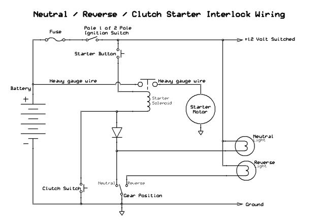
Here is how it works. The starter solenoid needs to have 12 volts across its actuating coil (the small wires). When 12 volts DC is applied the coil draws about 3 amps. This generates a magnetic field that sucks down a spring loaded steel plate that shorts the two big terminals together (connecting the battery directly to the starter).
The top side of the solenoid actuating coil is supplied 12 volts through the fuse, ignition switch, and the start button. The other side of the actuating coil is grounded though either of the following:
1) When the quad is in neutral the solenoid actuating coil wire is grounded by the Neutral switch through the diode (which is forward biased.
2) Or if the clutch is pulled in the clutch switch grounds the solenoid actuating wire directly.
Note how the gear position switch also grounds the neutral and reverse lights. Also note how the other side of the two lights are tied to switched and fused +12 volts.
The diode allows the clutch to be pulled in and allow starting without also lighting up the neutral light - which would be confusing, but it wouldn't hurt anything. When the quad is not in neutral and the clutch is pulled in, the diode is reverse biased and blocks current flowing through the neutral light through the clutch switch. So the neutral light stays off.
I included the reverse indicator light because it is mentioned in your post, and because it is part of the neutral/reverse switch. Note that the reverse switch is not actually involved in the starter interlock circuitry.
I hope this makes some sense. Come back if you have any questions...
Look at the diagram below. This is how the starter interlock is typically wired up where the safety interlock is the clutch and/or neutral switch instead of using the brake switch.
The delay in responding is because I had to make this diagram from a mix of mostly unreadable diagrams to diagrams that are riddled with errors. Here it is:
Here is how it works. The starter solenoid needs to have 12 volts across its actuating coil (the small wires). When 12 volts DC is applied the coil draws about 3 amps. This generates a magnetic field that sucks down a spring loaded steel plate that shorts the two big terminals together (connecting the battery directly to the starter).
The top side of the solenoid actuating coil is supplied 12 volts through the fuse, ignition switch, and the start button. The other side of the actuating coil is grounded though either of the following:
1) When the quad is in neutral the solenoid actuating coil wire is grounded by the Neutral switch through the diode (which is forward biased.
2) Or if the clutch is pulled in the clutch switch grounds the solenoid actuating wire directly.
Note how the gear position switch also grounds the neutral and reverse lights. Also note how the other side of the two lights are tied to switched and fused +12 volts.
The diode allows the clutch to be pulled in and allow starting without also lighting up the neutral light - which would be confusing, but it wouldn't hurt anything. When the quad is not in neutral and the clutch is pulled in, the diode is reverse biased and blocks current flowing through the neutral light through the clutch switch. So the neutral light stays off.
I included the reverse indicator light because it is mentioned in your post, and because it is part of the neutral/reverse switch. Note that the reverse switch is not actually involved in the starter interlock circuitry.
I hope this makes some sense. Come back if you have any questions...
Jun 28, 2012 | 05:47 PM
#7
Thread Starter
|
Weekend Warrior
Joined: Jun 2012
Posts: 12
Likes: 0
Lynn Thanks SO MUCH for this diagram, It worked perfect and I was able to figure out my lights, got them hooked up and working great now. Here's some pics of my new wiring harness that I built here at home with a few Aircraft parts from work ( ...LOL..) Ive got most of it hooked up, wrapped and secured in place. Im working my way up towards the gas tank and into the front faring to do my final wire splices. You guys check it out and tell me what ya think.


You guys check it out and tell me what ya think.
Trending Topics
Jun 28, 2012 | 11:03 PM
#8
Electrical Expert
Likes High Voltage In The Tub!
Likes High Voltage In The Tub!
Joined: Dec 2008
Posts: 3,260
Likes: 14
From: Tracy, California, USA
Your welcome for the help. When I went to look at diagrams for the clutch/neutral/reverse interlock wiring I found quite a few, but they all had the same glaring error replicated across different brands. Apparently the first one to publish had their obvious error copied over and over... SO I redrew it...
I'm glad you got it working. Nice job on the wiring. It does look aircraft quality .
.
I'm glad you got it working. Nice job on the wiring. It does look aircraft quality
.
Jun 29, 2012 | 02:18 AM
#9
Thread Starter
|
Weekend Warrior
Joined: Jun 2012
Posts: 12
Likes: 0
Thanks Lynn!!! . Couldn't have done it all without your help and knowledge.
I have another question concerning my new wiring and charging system. I wanted to add a set of HID lights or Fog lights to the front end of my Quad but was wondering what effect it would have on my charging system or if it could even handle it without burning something up. I still plan on using my front factory headlights but just wanted to add extra lights for night time trail riding. Would I need to run a Digital Ballast*like what is used on HID lights to help power up the light without burning up my new wire harness??
Would I need to re-run a bigger gauge wire for my Fog & Headlights??
. Couldn't have done it all without your help and knowledge. I have another question concerning my new wiring and charging system. I wanted to add a set of HID lights or Fog lights to the front end of my Quad but was wondering what effect it would have on my charging system or if it could even handle it without burning something up. I still plan on using my front factory headlights but just wanted to add extra lights for night time trail riding. Would I need to run a Digital Ballast*like what is used on HID lights to help power up the light without burning up my new wire harness??
Would I need to re-run a bigger gauge wire for my Fog & Headlights??
Jun 30, 2012 | 12:39 AM
#10
Electrical Expert
Likes High Voltage In The Tub!
Likes High Voltage In The Tub!
Joined: Dec 2008
Posts: 3,260
Likes: 14
From: Tracy, California, USA
You will not hurt anything by loading the stator down with more than it can power. Stators are inherently current limiting by nature. If you put too big a load on the voltage drops to 12.6 volts where the battery then takes up the slack and provides the rest of the required current. But that also means your battery is getting discharged instead of being charged up.
This is situation normal for most quads at idle with headlights on. The max output of the stator in watts is proportional to engine speed. At idle the output is pretty meager and can't keep up with the headlights, so the battery is draining even though the engine is running. But when you run up the engine speed the output increases. The stator (through the voltage regulator) is able to provide enough power to drive the headlights, and more. The regulator then pushes the voltage up to 14 volts (+/- 0.5 volts) which is *above* the battery voltage of 12.6 volts. This causes current to flow backwards through the battery charging it back up.
You need to see if you have enough stator capacity to drive all the loads and raise the battery voltage to 14.0 volts at a medium fast engine speed (say 3000 RPM). That way, on average over normal engine speed ranges, the battery on average keeps charged. At idle it won't, but on average (which includes higher output at higher engine speeds) it will keep up.
Here's how to tell: Take you meter and set it to measure "Current" on the 10 amp scale. Uusally this involves moving the red meter probe over to a special "10 amp" input jack as well as setting the scale properly. Remove the main fuse coming off the battery, and insert the meter across the two fuse clips in the harness. Now all current (other than the starter motor current which goes though it own heavy gauge wires) will pass through the meter and be measured directly. Leave the meter in position for the rest of the tests. Turn on the headlights and set to high beam. You should see the current being drawn by the headlights. Note the polarity.
Now start up the quad. The current being drawn out of the battery will be diminished since some of the load current is being provided by the stator through the regulator - the rest is coming from the battery. Rev up the engine. Look at the current values and the polarity. If your stator can keep up with the load you will see the current go to zero with increasing speeds, reverse polarity and climb back up. The reversing of current polarity (current direction) is where you've reached the break even point where the stator is powering (barely) all the electrical loads. At higher engine speeds then the break even point you are measuring the battery "charging" current.
HID lights and LED lights are much, much more efficient than stock incandescant lights in terms of watts consumed versus lumens out. If your stator can't keep up with the new lights then keep the new lights and scrap the stock lights. There are some really impressive you tube videos of HID and LED lighting systems for quads. The only down side to them is the initial cost ($$$).

Thread
Thread Starter
Forum
Replies
Last Post
Currently Active Users Viewing This Thread: 1 (0 members and 1 guests)