
05 Baja 90 atv no spark
 Jun 10, 2010 | 06:10 PM
#1

Thread Starter
|
Weekend Warrior
Joined: Jun 2010
Posts: 18
Likes: 0
I know this issues has been discussed often because this seems to be a common issue. I did use the search function, actually searching google is how i got here a million times... so to simplify things this is the issue, i got this atv from a friend who had it on the porch for 2 years, he got it new, it got stolen, then recovered. missing ignition key switch and the headlights, there was wires strung everywhere trynna hot wire the whole thing to get spark, well the ignition coil melted from the inside out. i got a coil off of a good running mini 90cc atv still no spark so i pulled out the trusty volt meter. I have a total of 6 wires on my CDI box and the speed governer is seperate from the CDI. there is a 4 wire plug and a 2 wire plug on the CDI. first the 4 wire plug. blue/white no voltage while pushing the start button, green: ground is fine, black yellow is .07 volts now for the 2 wire plug. black/red: 6.3-7.4 volts, but when the battery is charged more it only gave me like 3.7volts while pushin the start button which is the only time i get a reading it changes here and there, finally on that plug is black white which is the hot in and that gives me whatever the battery gives me with now that its been charging its up at 13.2v...
now off to the plug coming from the stator. total of 5 wires. black red carries identical voltage as the one at the CDI so i assume thats where it runs to, blue white carries nothing, there are 2 yellow and they both give me 0.5v and then green white carries nothing. im confused. o yea there is no key switch so i have red, black, and black/white all tied together and the green(ground) is just having and it provides a good ground when i used it as my ground souce for my volt meter. so any help would be awsome. i hope i provided enough info to avoid any questions that might arise about what CDI i have and all of the above. thanks in advance
now off to the plug coming from the stator. total of 5 wires. black red carries identical voltage as the one at the CDI so i assume thats where it runs to, blue white carries nothing, there are 2 yellow and they both give me 0.5v and then green white carries nothing. im confused. o yea there is no key switch so i have red, black, and black/white all tied together and the green(ground) is just having and it provides a good ground when i used it as my ground souce for my volt meter. so any help would be awsome. i hope i provided enough info to avoid any questions that might arise about what CDI i have and all of the above. thanks in advance
Jun 10, 2010 | 08:08 PM
#2
Thread Starter
|
Weekend Warrior
Joined: Jun 2010
Posts: 18
Likes: 0
well after further testing, i found that once i was fully fully charged it was funner to test, well anyhow on the cdi box the the black/red wire pumped out like 12-13v or so cant recall totally but i know it was double what it was giving me before. but the black/yellow wire which runs directly to the coil isnt putting anything out at all while cranking so i guess that means i need a new CDI? opinions please...
Jun 11, 2010 | 12:43 AM
#3

Electrical Expert
Likes High Voltage In The Tub!
Likes High Voltage In The Tub!
Joined: Dec 2008
Posts: 3,260
Likes: 14
From: Tracy, California, USA
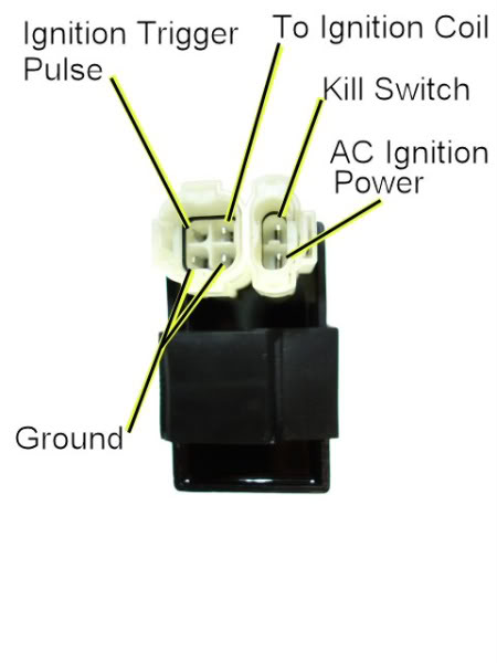
Is this your CDI?
If so we need to start over on your voltage measurements. They are all wrong.
To measure stator voltages (AC ignition power and Timing trigger) you must have the CDI disconnected. These voltages are AC (not DC). You must set your meter accordingly. Measure the voltages at the CDI connector pins to ground:
AC Ignition Power should be 80 volts AC while cranking the starter.
Timing Trigger voltage should be 0.2 to 0.5 Volts AC while cranking the engine.
The Yellow wires are AC voltages that charge the battery. That is important, but has nothing to do with spark. Ignore these wires and get spark, then later when the quad is running, lets come back and measure the battery charging system to see if this part is working.
Also measure your kill switch pin resistance to ground (in ohms) with all kill switches off.
I sent you a private email.
Jun 11, 2010 | 07:26 AM
#4
Thread Starter
|
Weekend Warrior
Joined: Jun 2010
Posts: 18
Likes: 0
for public purposes. i have the one that has the more boxed plugs, my measurements might be a bit off im trynna learn how to work with this. google is my friend, but i also feel like i was lookin for the wrong stuff.
Jun 11, 2010 | 12:25 PM
#5
Thread Starter
|
Weekend Warrior
Joined: Jun 2010
Posts: 18
Likes: 0
the ac ignition power was 80volts while crankin with the CDI disconnected. as far as the trigger i retested with cdi disconnected and i got no voltage while cranking. the blue/white wire on the 4 pin plug of the CDI gives me no reading on resistance to ground i dont mean 0 i mean no reading, and the green/white gives me the same thing. the reason i mention both of them is per my wiring diagram the bluewhite runs from the cdi to the kill switch, and the green white runs around the kill switch to the ground on the other end of it and also to a ground at the end of the magneto... all this is being tested with the cdi disconnected, and the kill switch wire i did with the switch turned off. one last thing i dont know how much this helps, but if i turn the on off(run) switch off on the handle bars and back on it will blow the fuse, but if i just leave it on and disconnect the battery its fine.
Jun 12, 2010 | 12:07 AM
#6
Electrical Expert
Likes High Voltage In The Tub!
Likes High Voltage In The Tub!
Joined: Dec 2008
Posts: 3,260
Likes: 14
From: Tracy, California, USA
I downloaded the baja 90 manual and pulled up the wiring diagram. Just as you report the diagram shows and "engine stop" switch between the trigger pulse from the stator and the CDI. So yes, this switch would have to be set in the "engine will run" condition to measure the trigger voltage.
But you also report that the green/white wire isn't shorted to ground. According to the wiring diagram it should be, but factory published wiring diagrams are notorious for containing colossal errors. It has to be grounded somewhere for the ignition trigger to work. Does the green/white wire hook up to the CDI connector in either of the two pins labeled "ground"? I'm thinking that maybe the ground side of the the trigger signal winding is really provided through the CDI which internally shorts those two ground pins together. You already said the solid green wire really is grounded.
So try measuring the trigger voltage between the blue/white wire and the green/white wire with the engine stop switch in the "run" position. See if you get trigger voltage of 0.2 to 0.5 volts AC while cranking the engine.
I'm not sure exactly what that "engine stop" switch in the wiring diagram is. Do you? There are two more conventional kill switches in the diagram: One is the kill switch side of the two pole ignition switch, and the other is a handle bar engine stop switch.
I've never taken apart the "more boxed" type CDI to see what's inside, but I bet the only difference is the connectors.
Jun 12, 2010 | 07:50 AM
#7
Thread Starter
|
Weekend Warrior
Joined: Jun 2010
Posts: 18
Likes: 0
from what i have seen with your diagram of the CDI box that u posted a pic of, its just a connector difference, the wire locations were the same. the engine stop switch is the handlebar switch, the only other kill switch provided on my ATV is the safety tether which is disconnected, i pulled the kill switch(black/white) wire from my CDI just to make sure that wasnt causing a problem. ill measure voltage on blue white and see whats gonig on there again, i think i was giving around .3volts when i last checked it, but i have to go back and double check. and ill see whats going on with that green/white. if its suppose to internally ground to fire off the coil then i might need a new CDI. also is my coil signal wire suppose to show 00.1 on continuity to ground when everything is plugged in
Trending Topics
Jun 12, 2010 | 10:14 PM
#8
Electrical Expert
Likes High Voltage In The Tub!
Likes High Voltage In The Tub!
Joined: Dec 2008
Posts: 3,260
Likes: 14
From: Tracy, California, USA
This sounds low, but it may be your meter. I measure 0.3 ohms on mine, which should be the same coil as yours. When you short your meter leads together does it read 0.0 ohms? You should not be reading the same value for the ignition coil primary resistance and the resistance of shorted meter leads. In ther words you should see some increase in resistance when comparing shorted meter leads to the measured coil reistance
Jun 12, 2010 | 10:38 PM
#9
Thread Starter
|
Weekend Warrior
Joined: Jun 2010
Posts: 18
Likes: 0
i got it running, after changing the fried coil and still not gettin spark i researched and it kept sayin to unplug the safety tether plug, useless, i took the 2 blue/white wires in the tether connect and spliced them together and my blue white at the CDI started giving me a reading, and from there i had spark, so i was just left to deal with the clogged dirty carb from having gas in it for over 2 years... thanx so much for the help that you provided me on the electrical diagnosis, i would have never known that the blue/white was suppose to give me a reading white cranking.
Jun 14, 2010 | 12:50 AM
#10
Electrical Expert
Likes High Voltage In The Tub!
Likes High Voltage In The Tub!
Joined: Dec 2008
Posts: 3,260
Likes: 14
From: Tracy, California, USA
...after changing the fried coil and still not gettin spark i researched and it kept sayin to unplug the safety tether plug, useless, i took the 2 blue/white wires in the tether connect and spliced them together and my blue white at the CDI started giving me a reading, and from there i had spark....
... thanx so much for the help that you provided me on the electrical diagnosis, i would have never known that the blue/white was suppose to give me a reading white cranking.
... thanx so much for the help that you provided me on the electrical diagnosis, i would have never known that the blue/white was suppose to give me a reading white cranking.