POLARIS IRS CV BOOT REPAIR REPLACMENT 00-09 may be other yrs
#1
 03-15-2009, 03:22 AM

Join Date: Nov 2008
Location: eden valley mn
Posts: 1,232
Likes: 0
Received 0 Likes
on
0 Posts
well after being on the polaris forum for awhile. iv seen alot of repeat topics on cv boot repair. cv shaft removal. and how tos. many ask the same question over and over. so since i have nothing better to do and it 1am here and im not tired. ill see if i can help alot of people on here. ill do he best i can. and also add my exsperiances with cv boots.
pics from polaris polaris repair manual of a 03 sportsman. but all polaris IRS are realy close to the same if not the same. my 00' sp 335 is the same as this. and by the looks of things on my new 08 its also the same.
so you want to fix your cv boot your self. good choice! save your money for other add ons on the atv. you might evon beable to spend more time wheeling insted of waiting for it to get fixed. this maybe also a good time to replace both cv boots. i have in the past replaced one boot then a short time later fix the other one. first boot replacment might take up to and hr or 2. but the more you do it will take less time.
REAR HUB REMOVAL
1. Place the ATV in Park and lock the parking brake.
Remove rear hub cap.
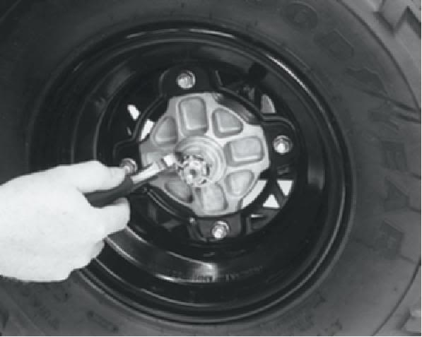
2. Remove cotter pin.
3. Loosen the hub retaining nut.
4. Loosen the wheel nuts.
5. Safely support the rear of the ATV.
CAUTION:
Secure the machine. Serious injury could occur
if machine tips or falls.
6. Remove wheel nuts and wheel.
7. Remove the rear brake caliper and safely
suspend the caliper from the frame with a piece of
wire.
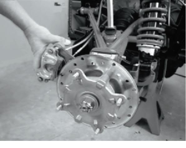
8. Remove hub nut, domed washer and flat washer.
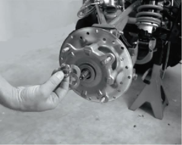
9. Remove hub.
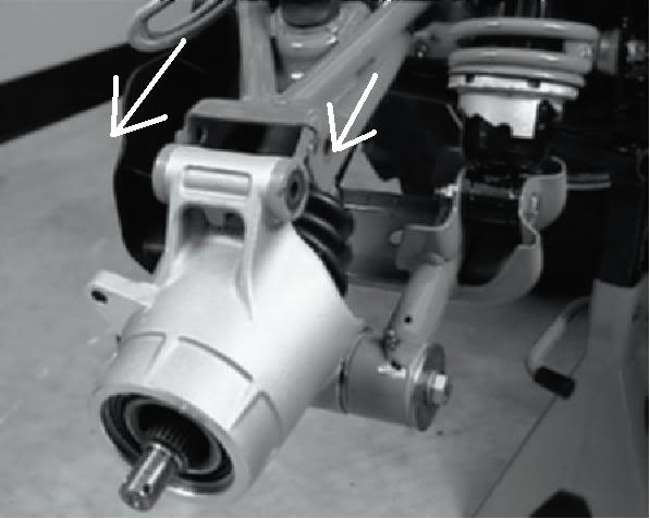
10. Remove upper control arm bolt as shown.
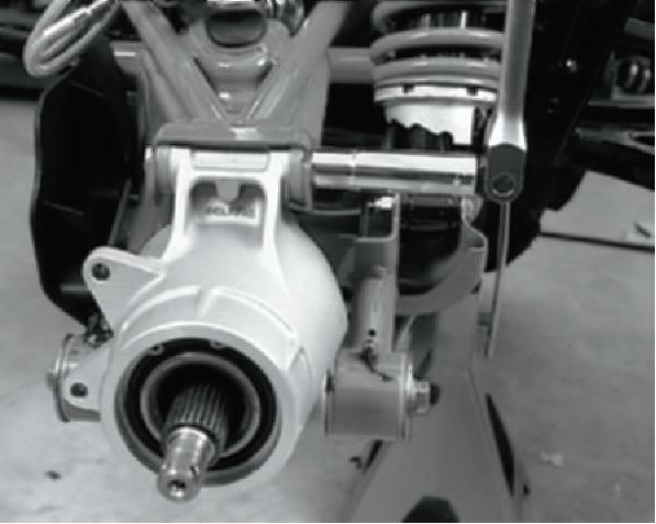
11. Remove both lower control arm bolts.
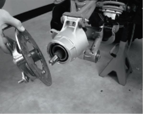
12. Remove bearing carrier.
REAR HUB INSTALLATION
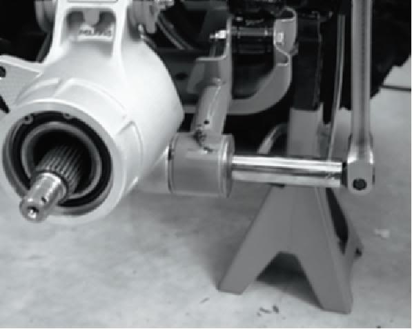
1. Insert bearing carrier on drive shaft.
2. Align bottom of carrier housing and lower control
arm. Grease and slide lower control arm
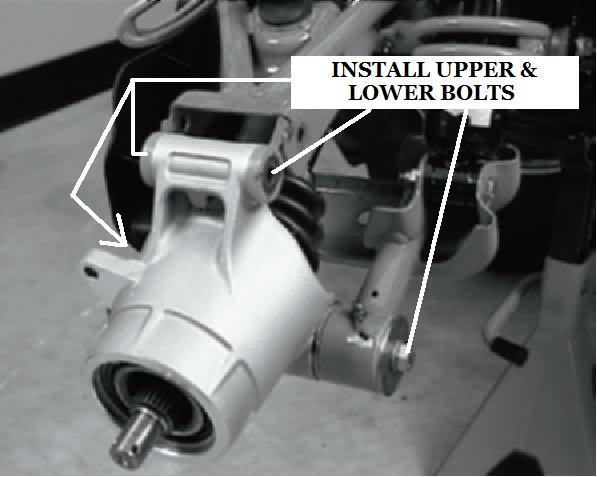
bushings into place, securing corner housing.
Install upper and lower bolts
Lower Control Arm Bolt Torque:
40 ft. lbs. (54 Nm)
Upper Control Arm Bolt Torque:
35 ft. lbs. (48 Nm)
3. Install and torque both lower control arm bolts.
4. Lift bearing carrier until top aligns with upper
control arm. Install and torque upper control arm
bolt and torque to specification.
Rear Hub Nut Torque:
80 ft. lbs. (109 Nm)
Rear Wheel Nut Torque
30 ft. lbs. steel 90ft. lbs for alum
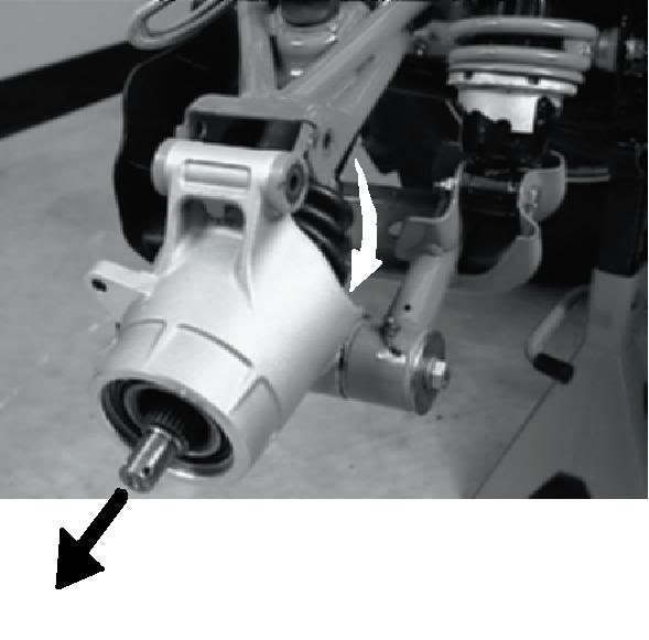
5. Pull drive shaft outward and install hub onto
driveshaft splines.
6. Install cone washers with domed side facing

outward.
7. Install retainer nut, wheel and wheel nuts.
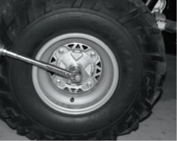
8. Remove jackstand and torque axle nut and wheel
nuts.
9. Install a new cotter pin. Tighten nut slightly to
align holes if required.
10. Install hub cap
REAR DRIVE SHAFT
REMOVAL
1. Remove rear hub and bearing carrier.
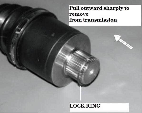
2. Tip hub outward and remove shaft from hub.
3. Pull sharply outward to remove shaft from
transmission. Install a new lock ring upon
assembly.
"iv never replaced my lock ring clip. Iv also used one or 2 pry bars and sliped it between the shaft and the transmission. And pry lightly all the way around tell it pops out from the transmission."
DRIVESHAFT AND CV JOINT
HANDLING TIPS
Care should be exercised during driveshaft removal
or when servicing CV joints. Driveshaft components
are precision parts.
Cleanliness and following these instructions is very
important to ensure proper shaft function and a
normal service life.
* The complete driveshaft and joint
should be handled by getting hold of
the interconnecting shaft to avoid
disassembly or potential damage to
the driveshaft joints.
* Over-angling of joints beyond their
capacity could result in boot or joint
damage.
* Make sure surface-ground areas
and splines of shaft are protected
during handling to avoid damage.
* Do not allow boots to come into
contact with sharp edges or hot
engine and exhaust components.
* The driveshaft is not to be used as a
lever arm to position other
suspension components.
* Never use a hammer or sharp tools
to remove or to install boot clamps.
* Be sure joints are thoroughly clean
and that the proper amount and type
of grease is used to refill when joint
boots are replaced and when joints
are cleaned. Refer to text for grease
capacity of CV joints and CV joint
boots.
REAR DRIVE SHAFT
INSTALLATION
1. Slide shaft assembly into bearing carrier hub.
2. Apply anti-seize compound to splines of shaft.
3. Install a new lock ring and install the shaft.
4. Lift bearing carrier into place and install bolt to
upper control arm. Torque bolt to 35 ft. lbs.
5. Install hub, flat washer, domed washer (domed
side out) and nut. Torque center hub nut to 80 ft.
lbs. (109 Nm). Install new cotter pin and hub cap.
Rear Hub Nut Torque:
80 ft. lbs. (109 Nm)
6. Install rear wheel and torque wheel nuts to
specification.
7. Grease all fittings thoroughly with Premium
U-Joint Lubricant (PN 2871551).
REAR DRIVE SHAFT
SERVICE
1. Remove clamps from rubber boot(s) using the
proper boot clamp pliers.
"iv used a needle nose pliers"
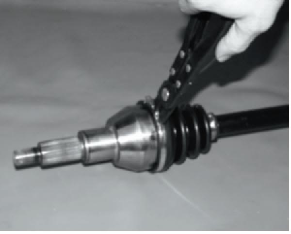
CV Boot Clamp Pliers:
Earless Type (PN 8700226)
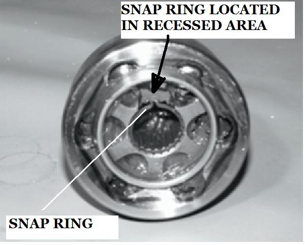
2. NOTE: Photo bellow is shown without shaft for
clarity. Wipe grease away from recess in CV joint
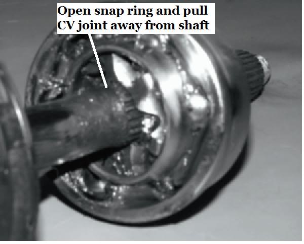
inner hub to locate snap ring.
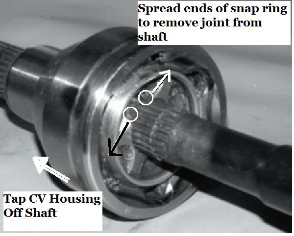
3. Open the snap ring using a snap ring pliers or
small needle nose pliers. Tap CV housing off
shaft with a soft faced hammer while holding snap
ring open.
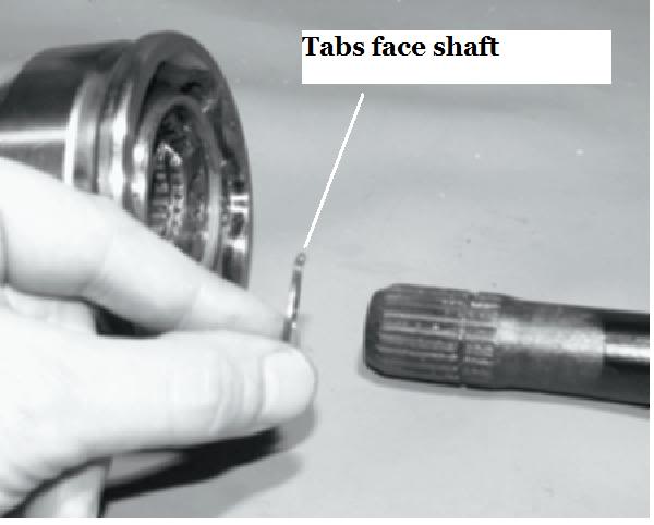
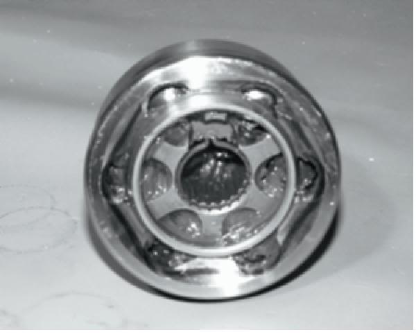
4. Place a new snap ring in the groove of the CV joint
inner hub, with tabs facing the shaft as shown.
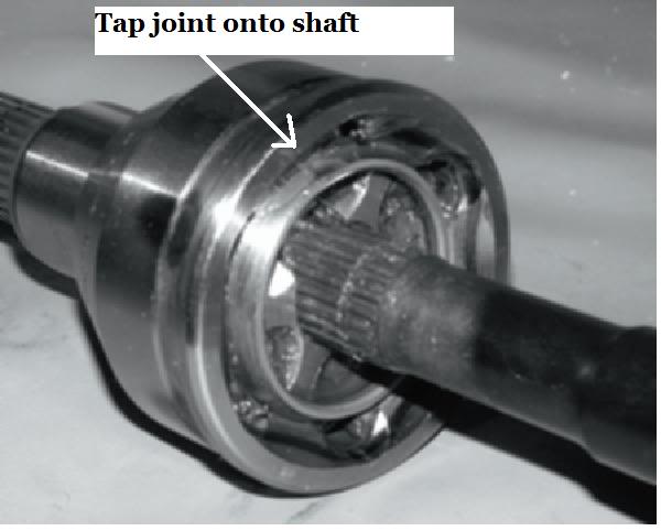
5. Refit CV joint on interconnecting shaft by tapping
with a plastic hammer on the joint housing. Take
care not to damage threads on the outboard CV
joint. The joint is fully assembled when the snap
ring is located in the groove on the
interconnecting shaft.
6. Install and tighten large boot clamp with boot
clamp pliers.
7. Remove any excess grease from the CV joint
external surfaces and position joint boot over
housing, making sure boot is seated in groove.
Position clamp over boot end and make sure
clamp tabs are located in slots. NOTE: Before
tightening boot clamp on inboard joint, make sure
any air pressure which may have built up in joint
boot has been released. The air should be
released after the plunging joint has been
centered properly. Tighten boot clamp using boot
clamp pliers. "needle nose pliers worked for me"
Boot Replacement
1. Remove CV joint from end of shaft.
2. Remove boot from shaft.
NOTE: When replacing a damaged boot, check the
grease for contamination by rubbing it between two
fingers. A gritty feeling indicates contamination. If
the grease is not contaminated, the boot can be
replaced without cleaning the CV joint. Use the
recommended amount of grease for boot
replacement only (see below). Proceed to Boot
Installation.
CV Joint Cleaning / Replacement
NOTE:Shiny areas in ball tracks and on the cage
spheres are normal. Do not replace CV joints because
parts have polished surfaces. Replace CV joint only
if components are cracked, broken, worn or otherwise
unserviceable.
3. Thoroughly clean and dry the CVjoint and inspect
ball tracks and cages for wear, cracks or other
damage.
4. Add the recommended amount of grease forCV
joint cleaning to the joint as shown below. Be
sure grease penetrates all parts of the joint.
Boot Installation
5. Fit joint boot and clamps on interconnecting shaft.
Make sure small end of boot is fully seated in
groove.
6. Position small clamp over small end of boot. Be
sure it is seated all the way around in the clamp
recess on the boot.
7. Tighten small boot clamp using boot clamp pliers.
8. Fill boot with grease supplied fromboot service kit
and spread evenly inside CV joint. Be sure to use
only the Constant Velocity Joint grease supplied
with boot service kit. NOTE: IF CV JOINT WAS
CLEANED, add the recommended amount of
grease to the joint in addition to the grease pack
supplied with boot kit.
Joint Capacity
OUTBOARD
80g Total
50 Grams
Boot Capacity
30 Grams
INBOARD
100g Total
Joint Capacity
50 Grams
Boot Capacity
50 Grams
NOTE: CV Joint Grease Capacity:
CV Joint Grease - 30g (PN 1350046)
50g (PN 1350047)
I hope this all works. Its took me about 2hrs to do this all. save pic to my comp. load to photobucket. copy text. etc. i might do the front cv axel next.
comment if you want.
chuck r.
pics from polaris polaris repair manual of a 03 sportsman. but all polaris IRS are realy close to the same if not the same. my 00' sp 335 is the same as this. and by the looks of things on my new 08 its also the same.
so you want to fix your cv boot your self. good choice! save your money for other add ons on the atv. you might evon beable to spend more time wheeling insted of waiting for it to get fixed. this maybe also a good time to replace both cv boots. i have in the past replaced one boot then a short time later fix the other one. first boot replacment might take up to and hr or 2. but the more you do it will take less time.
REAR HUB REMOVAL
1. Place the ATV in Park and lock the parking brake.
Remove rear hub cap.
2. Remove cotter pin.
3. Loosen the hub retaining nut.
4. Loosen the wheel nuts.
5. Safely support the rear of the ATV.
CAUTION:
Secure the machine. Serious injury could occur
if machine tips or falls.
6. Remove wheel nuts and wheel.
7. Remove the rear brake caliper and safely
suspend the caliper from the frame with a piece of
wire.
8. Remove hub nut, domed washer and flat washer.
9. Remove hub.
10. Remove upper control arm bolt as shown.
11. Remove both lower control arm bolts.
12. Remove bearing carrier.
REAR HUB INSTALLATION
1. Insert bearing carrier on drive shaft.
2. Align bottom of carrier housing and lower control
arm. Grease and slide lower control arm
bushings into place, securing corner housing.
Install upper and lower bolts
Lower Control Arm Bolt Torque:
40 ft. lbs. (54 Nm)
Upper Control Arm Bolt Torque:
35 ft. lbs. (48 Nm)
3. Install and torque both lower control arm bolts.
4. Lift bearing carrier until top aligns with upper
control arm. Install and torque upper control arm
bolt and torque to specification.
Rear Hub Nut Torque:
80 ft. lbs. (109 Nm)
Rear Wheel Nut Torque
30 ft. lbs. steel 90ft. lbs for alum
5. Pull drive shaft outward and install hub onto
driveshaft splines.
6. Install cone washers with domed side facing
outward.
7. Install retainer nut, wheel and wheel nuts.
8. Remove jackstand and torque axle nut and wheel
nuts.
9. Install a new cotter pin. Tighten nut slightly to
align holes if required.
10. Install hub cap
REAR DRIVE SHAFT
REMOVAL
1. Remove rear hub and bearing carrier.
2. Tip hub outward and remove shaft from hub.
3. Pull sharply outward to remove shaft from
transmission. Install a new lock ring upon
assembly.
"iv never replaced my lock ring clip. Iv also used one or 2 pry bars and sliped it between the shaft and the transmission. And pry lightly all the way around tell it pops out from the transmission."
DRIVESHAFT AND CV JOINT
HANDLING TIPS
Care should be exercised during driveshaft removal
or when servicing CV joints. Driveshaft components
are precision parts.
Cleanliness and following these instructions is very
important to ensure proper shaft function and a
normal service life.
* The complete driveshaft and joint
should be handled by getting hold of
the interconnecting shaft to avoid
disassembly or potential damage to
the driveshaft joints.
* Over-angling of joints beyond their
capacity could result in boot or joint
damage.
* Make sure surface-ground areas
and splines of shaft are protected
during handling to avoid damage.
* Do not allow boots to come into
contact with sharp edges or hot
engine and exhaust components.
* The driveshaft is not to be used as a
lever arm to position other
suspension components.
* Never use a hammer or sharp tools
to remove or to install boot clamps.
* Be sure joints are thoroughly clean
and that the proper amount and type
of grease is used to refill when joint
boots are replaced and when joints
are cleaned. Refer to text for grease
capacity of CV joints and CV joint
boots.
REAR DRIVE SHAFT
INSTALLATION
1. Slide shaft assembly into bearing carrier hub.
2. Apply anti-seize compound to splines of shaft.
3. Install a new lock ring and install the shaft.
4. Lift bearing carrier into place and install bolt to
upper control arm. Torque bolt to 35 ft. lbs.
5. Install hub, flat washer, domed washer (domed
side out) and nut. Torque center hub nut to 80 ft.
lbs. (109 Nm). Install new cotter pin and hub cap.
Rear Hub Nut Torque:
80 ft. lbs. (109 Nm)
6. Install rear wheel and torque wheel nuts to
specification.
7. Grease all fittings thoroughly with Premium
U-Joint Lubricant (PN 2871551).
REAR DRIVE SHAFT
SERVICE
1. Remove clamps from rubber boot(s) using the
proper boot clamp pliers.
"iv used a needle nose pliers"
CV Boot Clamp Pliers:
Earless Type (PN 8700226)
2. NOTE: Photo bellow is shown without shaft for
clarity. Wipe grease away from recess in CV joint
inner hub to locate snap ring.
3. Open the snap ring using a snap ring pliers or
small needle nose pliers. Tap CV housing off
shaft with a soft faced hammer while holding snap
ring open.
4. Place a new snap ring in the groove of the CV joint
inner hub, with tabs facing the shaft as shown.
5. Refit CV joint on interconnecting shaft by tapping
with a plastic hammer on the joint housing. Take
care not to damage threads on the outboard CV
joint. The joint is fully assembled when the snap
ring is located in the groove on the
interconnecting shaft.
6. Install and tighten large boot clamp with boot
clamp pliers.
7. Remove any excess grease from the CV joint
external surfaces and position joint boot over
housing, making sure boot is seated in groove.
Position clamp over boot end and make sure
clamp tabs are located in slots. NOTE: Before
tightening boot clamp on inboard joint, make sure
any air pressure which may have built up in joint
boot has been released. The air should be
released after the plunging joint has been
centered properly. Tighten boot clamp using boot
clamp pliers. "needle nose pliers worked for me"
Boot Replacement
1. Remove CV joint from end of shaft.
2. Remove boot from shaft.
NOTE: When replacing a damaged boot, check the
grease for contamination by rubbing it between two
fingers. A gritty feeling indicates contamination. If
the grease is not contaminated, the boot can be
replaced without cleaning the CV joint. Use the
recommended amount of grease for boot
replacement only (see below). Proceed to Boot
Installation.
CV Joint Cleaning / Replacement
NOTE:Shiny areas in ball tracks and on the cage
spheres are normal. Do not replace CV joints because
parts have polished surfaces. Replace CV joint only
if components are cracked, broken, worn or otherwise
unserviceable.
3. Thoroughly clean and dry the CVjoint and inspect
ball tracks and cages for wear, cracks or other
damage.
4. Add the recommended amount of grease forCV
joint cleaning to the joint as shown below. Be
sure grease penetrates all parts of the joint.
Boot Installation
5. Fit joint boot and clamps on interconnecting shaft.
Make sure small end of boot is fully seated in
groove.
6. Position small clamp over small end of boot. Be
sure it is seated all the way around in the clamp
recess on the boot.
7. Tighten small boot clamp using boot clamp pliers.
8. Fill boot with grease supplied fromboot service kit
and spread evenly inside CV joint. Be sure to use
only the Constant Velocity Joint grease supplied
with boot service kit. NOTE: IF CV JOINT WAS
CLEANED, add the recommended amount of
grease to the joint in addition to the grease pack
supplied with boot kit.
Joint Capacity
OUTBOARD
80g Total
50 Grams
Boot Capacity
30 Grams
INBOARD
100g Total
Joint Capacity
50 Grams
Boot Capacity
50 Grams
NOTE: CV Joint Grease Capacity:
CV Joint Grease - 30g (PN 1350046)
50g (PN 1350047)
I hope this all works. Its took me about 2hrs to do this all. save pic to my comp. load to photobucket. copy text. etc. i might do the front cv axel next.
comment if you want.
chuck r.


Thread
Thread Starter
Forum
Replies
Last Post
Rooky
Polaris Ask an Expert! In fond memory of Old Polaris Tech.
10
06-23-2015 09:35 PM
Currently Active Users Viewing This Thread: 1 (0 members and 1 guests)