
kazuma meerkat 50cc wiring diagram

 Feb 17, 2012 | 10:19 PM
#3

Electrical Expert
Likes High Voltage In The Tub!
Likes High Voltage In The Tub!
Joined: Dec 2008
Posts: 3,260
Likes: 14
From: Tracy, California, USA
I've never seen a Meerkat 50cc wiring diagram. I've seen lots of requests for one. I doubt any exist. I agree with BeyondUpNorth. Describe the problem first then we can form a plan of attack....
Feb 19, 2012 | 09:40 PM
#5
Electrical Expert
Likes High Voltage In The Tub!
Likes High Voltage In The Tub!
Joined: Dec 2008
Posts: 3,260
Likes: 14
From: Tracy, California, USA
So do you have the loom at all? Wiring up a whole quad from scratch is a challenge.
If you have a loom then why not just hook together what goes together, then see what works and what doesn't. Then we look at the stuff that doesn't work and figure out why...
If you have a loom then why not just hook together what goes together, then see what works and what doesn't. Then we look at the stuff that doesn't work and figure out why...
Feb 25, 2012 | 10:05 AM
#6

Thread Starter
|
Weekend Warrior
Joined: Feb 2012
Posts: 7
Likes: 0
iv got a loom but it has been opened up so its just a pile of wires with connectors iv connected all the connecters where i think they go. iv looked at some wiring diagrams that are simalar to it. now when i press the brake and press the start button it dosent turn over it blows the fuse iv looked to to see if any wirers are earthing on anything cant see any.iv cut the black/white wire the comes from cdi (cut out switches)to eliminate them.
Feb 25, 2012 | 01:12 PM
#7
Thread Starter
|
Weekend Warrior
Joined: Feb 2012
Posts: 7
Likes: 0
on the starter solinoid the two small wires coming out of it one goes to starter button should the other one go to a ground?
Trending Topics
Feb 25, 2012 | 10:53 PM
#8
Electrical Expert
Likes High Voltage In The Tub!
Likes High Voltage In The Tub!
Joined: Dec 2008
Posts: 3,260
Likes: 14
From: Tracy, California, USA
iv got a loom but it has been opened up so its just a pile of wires with connectors iv connected all the connecters where i think they go. iv looked at some wiring diagrams that are simalar to it. now when i press the brake and press the start button it dosent turn over it blows the fuse iv looked to to see if any wirers are earthing on anything cant see any.iv cut the black/white wire the comes from cdi (cut out switches)to eliminate them.
1) Turn on the ignition
2) Step on the brake
3) Press the start button
WHen you do those things in sequence one at a time, when exactly does the fuse blow?
If you can get to step 2 before the fuse blows, Does the brake light come on?
Feb 25, 2012 | 11:07 PM
#9
Electrical Expert
Likes High Voltage In The Tub!
Likes High Voltage In The Tub!
Joined: Dec 2008
Posts: 3,260
Likes: 14
From: Tracy, California, USA
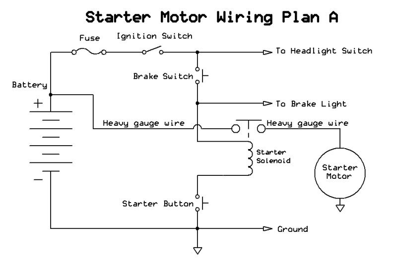
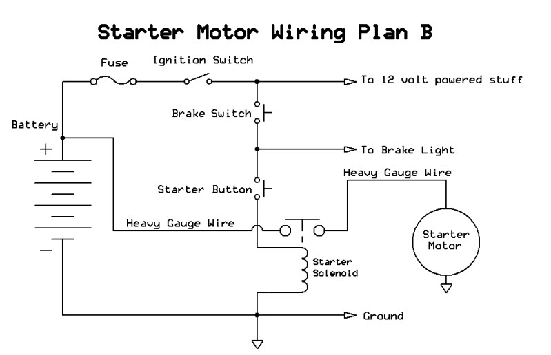
If I had to guess I would say the odds favour plan B for your quad. This is because it is easier to wire in generic remote start/stop/alarm modules with this scheme.
Both of them work essentially the same way. Lots of switches all wired nose to tail work to apply 12 volts *across* the two small wires on the starter solenoid.
Scheme "A" has all the switches on the plus side of things to the solenoid, with the other side of the solenoid directly tied to ground.
Scheme "B" has most of the switches applying 12 volts to one side if the small actuating wires, and the last switch (the start button) applying ground to the other side of the small wire actuating coil.
Feb 26, 2012 | 06:38 AM
#10
Thread Starter
|
Weekend Warrior
Joined: Feb 2012
Posts: 7
Likes: 0
just disconnected everything and connected it all back together with a new fuse. ignition on, brake on, brake light on,starter button working fuse is ok starter solenoid not working so going to get a new one. good guess it is plan b thanks for the diagrams ill have to wait for a new solenoid ill let you know how i get on when it arrives