
Roketa ATV-02 250 no spark
 Oct 6, 2011 | 07:23 PM
#11

Weekend Warrior
Joined: Oct 2011
Posts: 7
Likes: 0
In frustration of incorrect information found here as well as other places.
1, The Oval plug shaped CDI box is said to have the same Pinout locations and functions of the Square shaped Cdi Box.
This Is Incorrect.
The Square shaped Plugged CDI box was tested using the Oval shaped Pinout or Diagram. The Cdi Loudly Poped like a blowing capacitor. Note in this test the Pickup coils Polarity shall not cause such a damage as it should not Destroy the circuit in a loud bang as all it generates is 3.3 volts AC. Regardless the Pickup coils Polarity It should not have Malfuctioned the CDI.
The Cdi with the Square Plug does not match up to the one with the oval Plug. Any information on the Square Pluged CDI would be great!
For ********* sakes I cant upload a photo?
Oct 7, 2011 | 12:59 AM
#12

Electrical Expert
Likes High Voltage In The Tub!
Likes High Voltage In The Tub!
Joined: Dec 2008
Posts: 3,260
Likes: 14
From: Tracy, California, USA
I think photos are disallowed until you've posted like 20 times. This is a guard against spamming the forum I expect. I think that you can host pictures on free picture hosting web site like photobucket.com and link them in with no problems. Most of my pictures in this site are remotely hosted by photobucket.
To the best of my knowledge the square shaped CDI's are wired the same as the oval shaped CDI's. But there are limitations to my knowledge: I've never taken apart and traced out a square shaped connector CDI. I've only seen wiring diagrams and other posts suggesting they are the same. And even if I had taken apart a square shaped and found them to be the same, that would be no guarantee that somebody else hasn't made a weird off the wall CDI using the same connectors. Case in point: In the last couple weeks we had a couple threads about round connector 6 pin CDIs driving a dual cylinder engine with *two* coil outputs on the CDI (for two ignition coils to drive each cylinder separately) - using exactly the same connectors and looking like the *generic* chinese CDI that is available everywhere. Obviously they are not compatible with the generic CDI's - even though they look the same.
On the round connector 6 pin CDIs: There are two generic and very common versions - AC powered and DC powered. The pin out is the same except the power input pin can be moderately high voltage AC power, or 12 volts DC from the ignition switch. You can't tell by looking which is which. And they are not compatible. I wonder if the same thing isn't true of the square pin CDI's .
.
Also on the round pin CDIs: If you plug and AC powered CDI into a wiring harness configured for an identical looking DC powered CDI you often will get a loud bang, smoke and sometimes shrapnel coming out of the CDI. This sort of sounds like your situation.
So what's the whole story here? What quad model and year?
What happened to the old CDI? Why do you think it is bad?
I assume you plugged a new CDI into the quad and it went bang. Where did you get the new CDI? Can you provide a link to the site if you bought it online?
How did you get square and round connectors to mate together?
Do you know if your quad CDI wiring is set up for DC powered CDI's, or AC powered CDI's?
To the best of my knowledge the square shaped CDI's are wired the same as the oval shaped CDI's. But there are limitations to my knowledge: I've never taken apart and traced out a square shaped connector CDI. I've only seen wiring diagrams and other posts suggesting they are the same. And even if I had taken apart a square shaped and found them to be the same, that would be no guarantee that somebody else hasn't made a weird off the wall CDI using the same connectors. Case in point: In the last couple weeks we had a couple threads about round connector 6 pin CDIs driving a dual cylinder engine with *two* coil outputs on the CDI (for two ignition coils to drive each cylinder separately) - using exactly the same connectors and looking like the *generic* chinese CDI that is available everywhere. Obviously they are not compatible with the generic CDI's - even though they look the same.
On the round connector 6 pin CDIs: There are two generic and very common versions - AC powered and DC powered. The pin out is the same except the power input pin can be moderately high voltage AC power, or 12 volts DC from the ignition switch. You can't tell by looking which is which. And they are not compatible. I wonder if the same thing isn't true of the square pin CDI's
.Also on the round pin CDIs: If you plug and AC powered CDI into a wiring harness configured for an identical looking DC powered CDI you often will get a loud bang, smoke and sometimes shrapnel coming out of the CDI. This sort of sounds like your situation.
So what's the whole story here? What quad model and year?
What happened to the old CDI? Why do you think it is bad?
I assume you plugged a new CDI into the quad and it went bang. Where did you get the new CDI? Can you provide a link to the site if you bought it online?
How did you get square and round connectors to mate together?
Do you know if your quad CDI wiring is set up for DC powered CDI's, or AC powered CDI's?
Oct 7, 2011 | 11:10 AM
#13
Weekend Warrior
Joined: Oct 2011
Posts: 7
Likes: 0
Also on the round pin CDIs: If you plug and AC powered CDI into a wiring harness configured for an identical looking DC powered CDI you often will get a loud bang, smoke and sometimes shrapnel coming out of the CDI. This sort of sounds like your situation.
Sounds like it to me!I Posted A youtube video for this. And I think you're right...
CDI BOX - YouTube
Sounds like it to me!I Posted A youtube video for this. And I think you're right...
CDI BOX - YouTube
Oct 7, 2011 | 11:24 PM
#14
Electrical Expert
Likes High Voltage In The Tub!
Likes High Voltage In The Tub!
Joined: Dec 2008
Posts: 3,260
Likes: 14
From: Tracy, California, USA
I watched the video. Yikes...
(I really did enjoy it. It was entertaining to say the least... )
)
OK.
You first need to find out how your quad ignition system is wired. It is either DC powered or AC powered. Here is the procedure:
I suspect you'll find out that your CDI needs to be DC powered. But check it to see for sure...
Next:
You made some comments in your video about "bypassing the ignitor coil in the magneto". Lets make sure that we are talking the same terms here. There are one or possibly two coils in the stator that have to do with the ignition system. One coil is the small pickup coil mounted outside the flywheel. This generates a timing signal that tells the CDi when to fire. It is absolutely necessary and cannot be bypassed. The other coil is inside the flywheel and generates a moderately high voltage AC signal to power an AC powered CDI. This is not required if you have a DC powered CDI. And you can fairly easily rewire an AC powered quad to work with a DC powered CDI if you decide to switch over. But this is not for everybody. It involves wiring, which for many people is equivalent to undergoing eye surgery.
To repeat: 6 pin CDI's (2 and 4 pin connectors) can be DC powered and they can be AC powered. You've got to get the right one or it either won't work, or it will come apart (as you so eloquently showed in your video)
Now for the 5 pin CDI's versus the 6 pin CDIs:
I've taken a few of these apart and traced out the circuitry. Although 6 pin CDIs can be DC or AC powered, 5 pin CDI's are *always* AC powered.
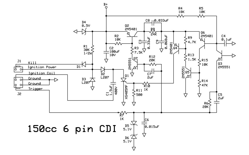
If you compare the internal circuitry on a 6 pin AC powered CDI to a 5 pin CDI (shockingly) they are exactly the same. Here it is:
First the AC powered 6 pin CDI:
Now for the 5 pin CDI (which is always AC powered):
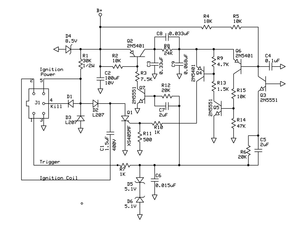
Note how it is exactly the same (except for the connectors of course).
Disclaimer: I know that the designs above are not the only CDI designs out there. I know this because I have seen other waveforms on the input/output pins of the CDi then the ones I've seen on the circuits above. And I have not taken any of those apart. So I don't know all the answers. But the ones above are the most common by far.
I think I have a youtube account, though I don't remember my account name or password. If I can dig it up I would like to reply to your video and direct them to this site (if they will allow it) so all can continue the discussion. But please don't take offense if I disagree on some points. I'm not criticizing you at all- I love the idea of free information exchange. I'm wrong all the time, and I may still be wrong here (but I don't think so). But fear of being wrong doesn't stop me. I post, and if I'm wrong the error gets corrected. The knowledge base grows and we all go on.
Your video will go a long way to expand the knowledge base...
(I really did enjoy it. It was entertaining to say the least...
)OK.
You first need to find out how your quad ignition system is wired. It is either DC powered or AC powered. Here is the procedure:
The 2 plug 6 wire CDIs come in two different designs. One is powered off 12 volts DC, and the other is powered off a moderately high voltage AC which comes from the stator. Unfortunately there is no reliable way to tell the difference between the two by just looking at them. To be sure you need to use a meter to find out which you have:
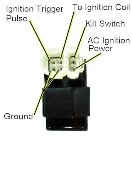
1) Unplug the CDI, and turn on the ignition. Do not crank the starter motor. Use a meter to measure the *DC* voltage on the pin labeled "AC ignition power" in the wiring harness to both ground pins in the 4 pin CDI connector. If you measure 12 volts DC then you have a DC powered CDI.
2) If you don't measure 12 volts DC on the ignition power pin, then switch the meter over to measure AC volts on the 200 volt scale. While cranking the starter motor, measure the AC voltage on the "AC Ignition Power" pin to the the Ground pin. You should see 40 to 80 volts AC. If you measure AC voltage when the starter is turning then you have an AC powered CDI.
Using a meter is the only 100% reliable way to figure out if your CDI is AC or DC powered. But there are some clues you can use that are usually (but not always) correct:
A) DC CDIs tend to be a little larger than their AC powered counterpart. This is because the DC powered CDI needs a bunch more circuitry to convert the 12 volts DC to the moderately high voltage supply that all CDIs must have.
B) Most (but not all) DC powered quad ignition systems do not use the kill switch input pin. The CDI connector pin usually has no wire tied to it. AC powered quad ignition systems usually do use the kill switch input pin.
Next:
You made some comments in your video about "bypassing the ignitor coil in the magneto". Lets make sure that we are talking the same terms here. There are one or possibly two coils in the stator that have to do with the ignition system. One coil is the small pickup coil mounted outside the flywheel. This generates a timing signal that tells the CDi when to fire. It is absolutely necessary and cannot be bypassed. The other coil is inside the flywheel and generates a moderately high voltage AC signal to power an AC powered CDI. This is not required if you have a DC powered CDI. And you can fairly easily rewire an AC powered quad to work with a DC powered CDI if you decide to switch over. But this is not for everybody. It involves wiring, which for many people is equivalent to undergoing eye surgery.
To repeat: 6 pin CDI's (2 and 4 pin connectors) can be DC powered and they can be AC powered. You've got to get the right one or it either won't work, or it will come apart (as you so eloquently showed in your video
)Now for the 5 pin CDI's versus the 6 pin CDIs:
I've taken a few of these apart and traced out the circuitry. Although 6 pin CDIs can be DC or AC powered, 5 pin CDI's are *always* AC powered.
If you compare the internal circuitry on a 6 pin AC powered CDI to a 5 pin CDI (shockingly) they are exactly the same. Here it is:
First the AC powered 6 pin CDI:
Now for the 5 pin CDI (which is always AC powered):
Note how it is exactly the same
(except for the connectors of course).Disclaimer: I know that the designs above are not the only CDI designs out there. I know this because I have seen other waveforms on the input/output pins of the CDi then the ones I've seen on the circuits above. And I have not taken any of those apart. So I don't know all the answers. But the ones above are the most common by far.
I think I have a youtube account, though I don't remember my account name or password. If I can dig it up I would like to reply to your video and direct them to this site (if they will allow it) so all can continue the discussion. But please don't take offense if I disagree on some points. I'm not criticizing you at all- I love the idea of free information exchange. I'm wrong all the time, and I may still be wrong here (but I don't think so). But fear of being wrong doesn't stop me. I post, and if I'm wrong the error gets corrected. The knowledge base grows and we all go on.
Your video will go a long way to expand the knowledge base...
Oct 8, 2011 | 09:01 AM
#15
Weekend Warrior
Joined: Oct 2011
Posts: 7
Likes: 0
I'm glad to learn I popped the igniter powered Cdi rather than a 12V one which is what I thought I had. You'de think you could ohm the Igniter/DC pin to see which you had?,,, What a protocol.. I figured the inside circuit resonated to death and went bang and started smoking,,, I just didn't know why..
I dont really like those schematics, They do not look legit. The size of the firing capacitor seems small to me..
Also, I cant seem to get them apart because of the Resin they're submerged in. is there a way I can cleanly take mine apart? Hrm.........
All of you guys have been great! Very comforting place here.... As the atv I have,,, Its a 220 Bayou Not sure which model,, Its not a new one at all. Has a igniter and pickup..
Pickup measures I think around 120 Ohms, and Igniter 140 Ohms. But stilll,,, Id rather have an electronic CDI. The Igniter is just another Problem to rule out I think.. Thanks for all the info. I'm not to crazy about them schematics...
I'm curious where those schematics came from? I cant seem to make any since of it, I'm looking for the firing capacitor...
Oct 8, 2011 | 08:42 PM
#16
Electrical Expert
Likes High Voltage In The Tub!
Likes High Voltage In The Tub!
Joined: Dec 2008
Posts: 3,260
Likes: 14
From: Tracy, California, USA
The capacitor is part of a resonant circuit, with the inductance of the ignition coil primary being the other half of the resonant pair. This is also resonant with the inductance of the ignition coil secondary winding and it's internal distributed (wire to wire) capacitance. By making the two ignition coil windings (primary and secondary) resonant, maximum power transfer between windings is achieved. If you make the primary less tuned to the natural resonant frequency of the secondary you get less power to the secondary, and get a weaker spark. Note that this "tuning" between primary and secondary is very broad. It not like tuning a radio where you have to be very precise. Plus or minus 30% in value is probably OK.
Here is an oscilloscope picture of what the ignition coil primary voltage looks like while cranking the engine. Voltage is on the Y axis against time on the X axis. The key point to notice is the voltage ringing at approximately 30 kilo hertz - illustrating the resonances involved...
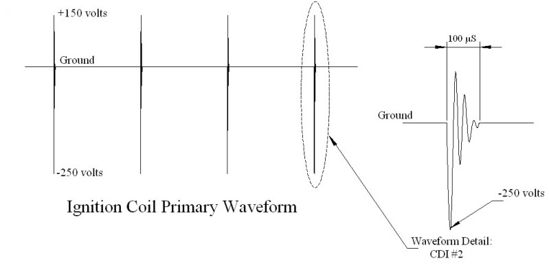 .
.The schematics were traced out and documented by me. I bought several CDI's and took them apart by prying out the black epoxy as outlined above.
Oct 13, 2011 | 02:40 AM
#17
Weekend Warrior
Joined: Oct 2011
Posts: 7
Likes: 0
I got the oval plugged shaped Cdi in and tested it out. The first rev of the hand crank and she fired once then no more after. I took a heat gun and dissasembled the circuit and found 11 electronic components.
4 diodes, 3 resisters, 3 capacitors, 1 transistor looking type thing.
This oval shaped CDI I have purchased again appears to be a Stator Igniter powered Cdi.
Now I am curiouse, I need the proper electronic Cdi. Here is the Ebay Link to the one I bought, Maybe I should contact them to see if they have the new one? Scooter CDI Box GY6 150cc 50cc Chinese Gy6 Moped ATV | eBay
Oct 13, 2011 | 02:59 AM
#18
Weekend Warrior
Joined: Oct 2011
Posts: 7
Likes: 0
Oct 13, 2011 | 11:58 PM
#19
Electrical Expert
Likes High Voltage In The Tub!
Likes High Voltage In The Tub!
Joined: Dec 2008
Posts: 3,260
Likes: 14
From: Tracy, California, USA
See the following PDF file from the SGS Thompson website (I think I can upload this):
SGS Thompson CDI App Note.pdf
Look down to figure 6 (assuming my pdf file upload works). It looks similar in parts count to the bare bones CDI you report (it's great you able to get the CDI apart BTW
). The problem is that this CDI design doesn't have any circuitry to protect against erroneous triggers caused by noise pickup. In the schematics posted above *most* of the circuitry is there to keep the CDI from firing at unbelievable times. Someone went to a lot of work to design CDIs that are a lot more immune to erroneous triggers, and this design has been implemented by multiple vendors. I really don't know how important it is for a quad ignition system to filter out erroneous trigger pulses. I have no experience here. Maybe a bare bones CDI works fine and nobody will know the difference. Or, it may be big problem. Again I don't know. But the fact that some designer (or designers) somewhere went to great extremes here has my curiosity peaked. Were they just over designing, or being due diligent?
Hmmm.
")
...This oval shaped CDI I have purchased again appears to be a Stator Igniter powered Cdi.
Now I am curiouse, I need the proper electronic Cdi. Here is the Ebay Link to the one I bought, Maybe I should contact them to see if they have the new one? Scooter CDI Box GY6 150cc 50cc Chinese Gy6 Moped ATV | eBay
Now I am curiouse, I need the proper electronic Cdi. Here is the Ebay Link to the one I bought, Maybe I should contact them to see if they have the new one? Scooter CDI Box GY6 150cc 50cc Chinese Gy6 Moped ATV | eBay
Last edited by LynnEdwards; Oct 14, 2011 at 12:01 AM. Reason: correct wrong info
Oct 14, 2011 | 12:03 AM
#20
Electrical Expert
Likes High Voltage In The Tub!
Likes High Voltage In The Tub!
Joined: Dec 2008
Posts: 3,260
Likes: 14
From: Tracy, California, USA