
Electrical Madness--CDI testing
 Nov 11, 2010 | 10:52 PM
#1

Thread Starter
|
Trailblazer
Joined: Sep 2010
Posts: 33
Likes: 0
To recap here are my first posts���.
Kazafog Posted:-
Just got this bike from a mate, its a 50cc quad, the only markings on it are shineray. It started yesterday and I ran it for 5 mins no problem then I stopped it and I haven't had spark since.
I've read some of the threads here and so far what I have done is measure the voltages at the CDI and I have 55ac at the ac ignition power pin and about 0.2ac at the trigger. The ground is definitely earthed and the kill switch input is not but is when the switch is in the off position (its a 5 pin CDI, with the pins all in the one plug). I get about 0.2ohms across the coil from the CDI plug and about 8kohm from each of the input leads to the output of the coil.
I also get only about 3Vac and 1 Vdc on the output of the CDI, ie If I disconnect the coil and measure across those 2 leads. I would think this is where the output of the capacitor should be, so it should be a high voltage (100~200Vdc) is that correct?
So my questions are
--is 55vac high enough to drive the CDI, or is the stator no good?
--are all these 5 pin CDIs the same, as I can buy one that looks exactly the same on ebay to suit a 110~125cc thumpstar?
--If they are not the same where can I buy one to suit the 50cc?
any help will be greatly appreciated.
LynnEdward:-
The nice thing about having the generic 5 pin CDI is that means you also have a generic coil. The coil and CDI are tuned to each other, so it means you can use any quad coil with your quad as long as the other quad also uses the same generic 5 pin CDI. You'll have to make it fit mechanically, but other than that they will be the same.
The coil resistances on my generic coil are 0.3 ohms on the primary to ground, and 8700 ohms (8.7K Ohms) on the secondary to ground. This can vary a bit from coil to coil on the primary side. On the secondary side it can vary all over creation. A lot of coils (mine included) have resistors built in to reduce radio interference emissions. Sometimes this resistor is on a removable plastic cap at the spark plug end. Other times it is not removable (like mine). I've never seen one, but some have reported coils with no resistor at all and secondary resistances of 12 to 20 ohms (0.012 to 0.020 K Ohms).
Measuring coil resistances are fine (and useful) when looking for opens or shorts, but it isn't very diagnostic for many common problems. If you have a shorted turn in the primary or secondary it won't affect the resistances much, but it will absolutely kill any spark. The other problem is with high voltage breakdown inside the coil (or sparkplug). You can't measure this with a meter. So the scheme is to measure and find (or eliminate) problems on the low voltage end of things, then if necessary change out the spark plug, coil, and (sometimes) the CDI.
Kazafog Posted:-
Thanks again for the info. My resistances on the coil are much the same as yours 0.3 and 8k7.
I might be lucky and the CDI will do it.
Kazafog Posted:-
its a piece of crap this thing, I got my new CDI and it worked for 5 min. Now no spark again.
I have removed the CDI and tested again and I get about 55vac at the ignition power pin and 0.3v or so at the trigger. Also about 370 ohms ground to ignition power pin and 120 ohms trigger to ground.
I noticed that if I check the ignition power with the CDI in place the volts are 0.7vac, does that sound right?
Anything ideas about anything else I can try, maybe the coil is stuffed although all the resistances are still the same as above?
thanks in advance
ps just ordered a new coil aswell.
LynnEdward:-
Your measurement of 0.7 volts AC on the AC power pin with the CDI plugged in is wrong. You still get good voltage on this pin with the CDI disconnected. This points to the CDI being bad.
The fact that it worked for 5 minutes also suggests that the original CDI was problem, the new CDI fixed it, the new CDI then failed, and your back with the same problem.
This is a good example of why you *must* measure the stator AC ignition power with the CDI disconnected. The CDI can (and does even in normal operation) jack around the AC ignition power from the stator. Thus when there is a problem it is impossible to determine if the stator or the CDI is at fault unless you measure voltages with them disconnected from each other.
Ordering a new coil is fine, but what I really think will fix the problem is ordering a new CDI from a different source.
Kazafog Posted:-
second CDI died after 5 min also, admittedly it was from the same source but.... does anyone know a reputable source for the 5 pin CDI boxes?
Also is there anyway that the bike could have something else wrong with it which is killing the CDIs, maybe?
Any ideas would be greatly appreciated. The kids still haven't got the ride this thing and we've had it for 3 weeks or so, very annoying.
Righty-o hopefully this works, and hopefully you can read it. Ignore the cap and resistor that are crossed out and the new line I drew to short them out, I compared the circuit to the silicon chip basic circuit and I think you could leave them out.
The large dots with a number beside them are the plug pins. I numbered them left to right top to bottom, like this.
1 - 2
3 4 5
The drawing out to the right was the board layout, as I may reuse the board with new components.
Its very basic thats for sure. The resistors values etc were gained using my fluke. I checked the datasheet on the SCR and it was 2 or 3 amps which I'm thinking maybe the problem. The resistors were all the small blue type 1/4watt I think.
Anyway see what you think, I am going to put the circuit into electronics workbench when I get a chance and see if I can get a working simulation.
Kazafog Posted:-
Just got this bike from a mate, its a 50cc quad, the only markings on it are shineray. It started yesterday and I ran it for 5 mins no problem then I stopped it and I haven't had spark since.
I've read some of the threads here and so far what I have done is measure the voltages at the CDI and I have 55ac at the ac ignition power pin and about 0.2ac at the trigger. The ground is definitely earthed and the kill switch input is not but is when the switch is in the off position (its a 5 pin CDI, with the pins all in the one plug). I get about 0.2ohms across the coil from the CDI plug and about 8kohm from each of the input leads to the output of the coil.
I also get only about 3Vac and 1 Vdc on the output of the CDI, ie If I disconnect the coil and measure across those 2 leads. I would think this is where the output of the capacitor should be, so it should be a high voltage (100~200Vdc) is that correct?
So my questions are
--is 55vac high enough to drive the CDI, or is the stator no good?
--are all these 5 pin CDIs the same, as I can buy one that looks exactly the same on ebay to suit a 110~125cc thumpstar?
--If they are not the same where can I buy one to suit the 50cc?
any help will be greatly appreciated.
LynnEdward:-
The nice thing about having the generic 5 pin CDI is that means you also have a generic coil. The coil and CDI are tuned to each other, so it means you can use any quad coil with your quad as long as the other quad also uses the same generic 5 pin CDI. You'll have to make it fit mechanically, but other than that they will be the same.
The coil resistances on my generic coil are 0.3 ohms on the primary to ground, and 8700 ohms (8.7K Ohms) on the secondary to ground. This can vary a bit from coil to coil on the primary side. On the secondary side it can vary all over creation. A lot of coils (mine included) have resistors built in to reduce radio interference emissions. Sometimes this resistor is on a removable plastic cap at the spark plug end. Other times it is not removable (like mine). I've never seen one, but some have reported coils with no resistor at all and secondary resistances of 12 to 20 ohms (0.012 to 0.020 K Ohms).
Measuring coil resistances are fine (and useful) when looking for opens or shorts, but it isn't very diagnostic for many common problems. If you have a shorted turn in the primary or secondary it won't affect the resistances much, but it will absolutely kill any spark. The other problem is with high voltage breakdown inside the coil (or sparkplug). You can't measure this with a meter. So the scheme is to measure and find (or eliminate) problems on the low voltage end of things, then if necessary change out the spark plug, coil, and (sometimes) the CDI.
Kazafog Posted:-
Thanks again for the info. My resistances on the coil are much the same as yours 0.3 and 8k7.
I might be lucky and the CDI will do it.
Kazafog Posted:-
its a piece of crap this thing, I got my new CDI and it worked for 5 min. Now no spark again.
I have removed the CDI and tested again and I get about 55vac at the ignition power pin and 0.3v or so at the trigger. Also about 370 ohms ground to ignition power pin and 120 ohms trigger to ground.
I noticed that if I check the ignition power with the CDI in place the volts are 0.7vac, does that sound right?
Anything ideas about anything else I can try, maybe the coil is stuffed although all the resistances are still the same as above?
thanks in advance
ps just ordered a new coil aswell.
LynnEdward:-
Your measurement of 0.7 volts AC on the AC power pin with the CDI plugged in is wrong. You still get good voltage on this pin with the CDI disconnected. This points to the CDI being bad.
The fact that it worked for 5 minutes also suggests that the original CDI was problem, the new CDI fixed it, the new CDI then failed, and your back with the same problem.
This is a good example of why you *must* measure the stator AC ignition power with the CDI disconnected. The CDI can (and does even in normal operation) jack around the AC ignition power from the stator. Thus when there is a problem it is impossible to determine if the stator or the CDI is at fault unless you measure voltages with them disconnected from each other.
Ordering a new coil is fine, but what I really think will fix the problem is ordering a new CDI from a different source.
Kazafog Posted:-
second CDI died after 5 min also, admittedly it was from the same source but.... does anyone know a reputable source for the 5 pin CDI boxes?
Also is there anyway that the bike could have something else wrong with it which is killing the CDIs, maybe?
Any ideas would be greatly appreciated. The kids still haven't got the ride this thing and we've had it for 3 weeks or so, very annoying.
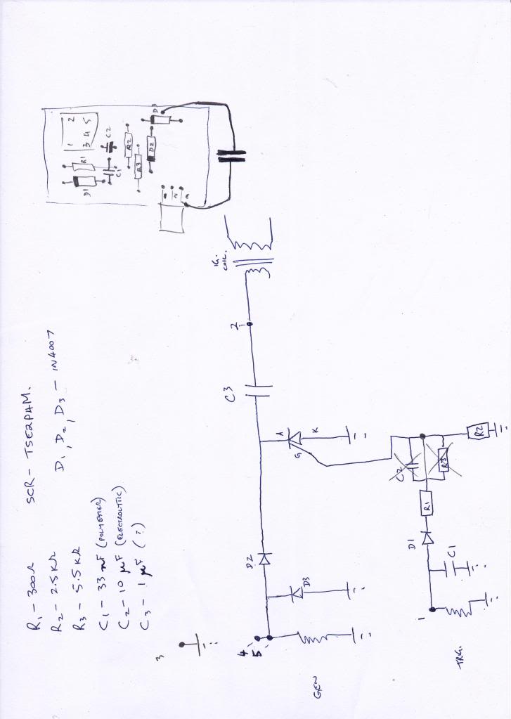
Righty-o hopefully this works, and hopefully you can read it. Ignore the cap and resistor that are crossed out and the new line I drew to short them out, I compared the circuit to the silicon chip basic circuit and I think you could leave them out.
The large dots with a number beside them are the plug pins. I numbered them left to right top to bottom, like this.
1 - 2
3 4 5
The drawing out to the right was the board layout, as I may reuse the board with new components.
Its very basic thats for sure. The resistors values etc were gained using my fluke. I checked the datasheet on the SCR and it was 2 or 3 amps which I'm thinking maybe the problem. The resistors were all the small blue type 1/4watt I think.
Anyway see what you think, I am going to put the circuit into electronics workbench when I get a chance and see if I can get a working simulation.
Nov 11, 2010 | 10:53 PM
#2
Thread Starter
|
Trailblazer
Joined: Sep 2010
Posts: 33
Likes: 0
LynnEdward:-
It is certainly is a lot simpler than the diagram I posted. The main difference is that the one I posted goes to great length to add noise immunity to the trigger input. In order to trigger the CDI you must "arm" the circuit on the positive trigger pulse, then it will fire on the negative half of the trigger pulse. The key is that the CDI design requires a small delay between the arm and trigger half cycles in order to fire the SCR, thus it will ignore transient spikes that would have any plus/minus ringing back to back. At least that is how I think it works. I haven't modeled it in spice or anything. Maybe I will someday when I have some free time.
Is lack of noise immunity a problem? I don't know. I've read two reports where quads have problems with starter teeth stripping, or the chain that the starter drives is breaking multiple times randomly, and for unknown reasons. The problems were never succesfully resolved - they just faded away - but I often wonder if the CDI was sometimes erroneously firing too soon. If the spark happens on the compression stroke too early it will try to push the piston back down going the wrong way. This won't happen if the engine is running (too much inertia), but during slow cranking I wonder. If you've ever had a pull start motor with timing set well before TDC you will know what I mean. You pull not quite fast enough and it will feel like your arm just got broken. On a quad if the engine attempts to go backward the starter clutch will stay locked up. The starter is torqued full out going forward, and the engine attempts to instantly reverse it (and going backwards it is geared way up to boot). Something has to give. In my pull rope example it was alway my fingers that couldn't hold on to the rope (after hammering my arm).
Somebody somewhere went to a lot of effort and expense to put all those extra parts in there. I'm betting there is a reason. I suspect the chinese didn't design this - it was probably copied from existing technology.
On your schematic C3 needs to be a really high voltage cap, and needs to be able to take plus and minus voltages (no electrolytics). The ripple current is fairly high, so choose a capacitor that has low equivalent series resistance (ESR). Also the capacitance value is chosen such that the capacitor resonates with the coil's primary winding inductance so that it matches the resonant frequency of the coil secondary winding and it's distributed capacitance. You get maximum energy transfer through the coil tht way.
The SCR needs to be heat sunk.
I've taken apart several CDI's and have never seen one as simple as the one you have. This is very interesting. Did they put gravel on your PCB before pouring in the epoxy resin? That makes it much harder to take apart on CDI's with through hole parts. With surface mount parts it is much easier.
LynnEdward:-
For the ignition system to work on your quad (5 pin CDI) you need to have:
1) Power to the CDI (AC moderately high voltage from stator)
2) A trigger pulse to the CDI (small signal AC voltage from stator)
3) The kill switch pin at the CDI must not be grounded
4) The CDI must have a ground (and the CDI must be good)
5) The Coil must be hooked up and working.
6) The spark plug must be working.
Kazafog Posted:-
armagh,
thanks for the concern. I don't know why but I haven't been getting any messages saying that this conversion had continued. So I was waiting till I had some more news to post.
But yesterday i got another CDI from a different source and blew it up too. But this time something else happened as well, which I don't understand.
This time I had the bike running a I turned the ignition switch off and a fuse that is connected to the battery blew. It was a 20Amp fuse. This stopped the lights and starter motor. I replaced the fuse which fixed the lights and starter but now the CDI is dead.
It seems as though the charging circuit and the CDI power or trigger coils are shorting, maaaaaybeee.... I don't understand it at all. The fuse shouldn't have anything to do with the CDI, or so i thought.
This is getting ridiculous. I'm going to have to bell out all the wiring to see what is going on. I have a drawing that someone else posted here so I'll start with that.
Any ideas would be greatly appreciated, because I'm nearly out.
here is a wiring diagram that I found in another post here. it may help someone. The fuse that blew is in the right top corner, I'm just not sure if the rest of the wiring matches yet, but I'm sure it'll be close.
 Nov 12, 2010 | 12:19 AM
#6

Electrical Expert
Likes High Voltage In The Tub!
Likes High Voltage In The Tub!
Joined: Dec 2008
Posts: 3,260
Likes: 14
From: Tracy, California, USA
A 20 amp fuse is way too high a value. A 7 or 10 amp is fuse more appropriate. My high output 8 pole 150cc quad stator can put out about 55 watts maximum at high engine speed, and that is supposed to be able to run everything on the quad, which is pretty much two headlights with high beam - the rest is trivial. 55 watts is a little less than 5 amps, so there is no downside to fusing at something like 10 amps on my quad. There is a big downside at fusing your quad at greater current values: You can blow stuff up that might survive with the fuse popping at a lower current.
I agree that the fuse should have nothing to do with the CDI since your CDI is AC powered. And maybe your current problem isn't related. It may all be happenstance.
I'm looking at your schematic of the 5 pin CDI, and mine too. If you plug your recently expired CDI back in does it blow (10 amp) fuses? Are you sure you most recent CDI is bad? Sometimes past experiences can prejudice current thinking into making hasty and wrong conclusions.
The only vulnerable input to the CDI that I can think of is the AC power input pin. There are many posted instances of people plugging in an AC powered CDI into a DC powered system and getting a blown up CDI as a result. These have all been on the 2 connector 6 pin CDI's (where the DC powered CDIs and the AC powered CDI's look identical). But having taken a couple of those AC powered 6 pin CDIs apart I can say with certainty that many of those are exactly the same circuitry inside as the generic five pin CDI - other than the connector(s) of course.
If it were me I would splice in an inline fuse going to the CDI power pin. I would put in a 1 amp fuse here. If this fuse ever blows then it would tell us this is the avenue by which the CDI's are being blown up, and hopefully the fuse will go in time to protect the CDI.
Another thought: On your simpler cdi schematic note that the kill switch pin and the AC power input pin are tied together inside the CDI. Onthe schematic I posted there is a diode between those two pins. It is completely legitimate to kill spark by shorting the AC power input to ground as in your schematic because the output of the stator is current limited to a safe value. But that kill switch to ground short comes form your ignition switch being turned off, and also on that ignition switch is 12 volts from the battery (through the fuse). If your ignition switch is bad it is possible that 12 volts got shorted inside the switch to the kill switch wire while you were turning off the ignition. If your kill switch wire is connected internally to the AC power ignition wire (as in your schematic) then this is a possible failure mode.
If your most recent CDI design resembles my posted schematic then the diode D1 would prevent that failure mode. So you might want to measure the resistance between the AC power Pin and the Kill Switch pin on your CDI and see if you get a short or a diode connection.
Nov 14, 2010 | 08:03 PM
#7
Thread Starter
|
Trailblazer
Joined: Sep 2010
Posts: 33
Likes: 0
Finally found the time to strip the quad. I didn't bother tracing all the wiring as I found that 3 wires had worn through, right beside the NEW ill fitting pod filter the guy that owned it before me put on. Just so happens the 3 wires were the AC power supply to the CDI and a positive straight from the fuse that blew and a negative straight from the battery.
So I'm thinking the AC and DC must have been coming in contact when I'd take it for a ride (it'd make it around the house once if I was lucky) which would kill the CDI (maybe) then the positive would find the negative or earth every so often which would blow the fuse.
What do you think does that sound feasible?
Trending Topics
Nov 16, 2010 | 12:33 AM
#10
Electrical Expert
Likes High Voltage In The Tub!
Likes High Voltage In The Tub!
Joined: Dec 2008
Posts: 3,260
Likes: 14
From: Tracy, California, USA
Finally found the time to strip the quad. I didn't bother tracing all the wiring as I found that 3 wires had worn through, right beside the NEW ill fitting pod filter the guy that owned it before me put on. Just so happens the 3 wires were the AC power supply to the CDI and a positive straight from the fuse that blew and a negative straight from the battery.
So I'm thinking the AC and DC must have been coming in contact when I'd take it for a ride (it'd make it around the house once if I was lucky) which would kill the CDI (maybe) then the positive would find the negative or earth every so often which would blow the fuse.
What do you think does that sound feasible?
So I'm thinking the AC and DC must have been coming in contact when I'd take it for a ride (it'd make it around the house once if I was lucky) which would kill the CDI (maybe) then the positive would find the negative or earth every so often which would blow the fuse.
What do you think does that sound feasible?
On the other hand, chaffed wire bundles tend to wear down and short to the thing that is chaffing them - i.e. the frame. It seems to me less likely that that two wires in the bundle would somehow short to each other, and not to the frame that was causing the problem. It seems far fetched, but sometimes far fetched things happen (but they don't happen over and over). Maybe the chaffing surface was plastic (or some other non conductor)? Then two wires could wear *way* down without problems until they short...

First make sure you replace the main fuse to a reasonable value like 7 amps. Make sure your CDI really is bad, and that you're not jumping to conclusions based on past issues. If your CDI is bad again I would put in a inexpensive 1 amp in line fuse with the CDI power.
Do you know if the last bad CDI did or did not have a wire connection between the kill switch pin and the AC power input pin? This is a major difference between the schematic of your simple CDI versus the one I posted (which I think is more common).