
2007 Jetmoto No Spark...
 Dec 18, 2011 | 02:43 PM
#1

Thread Starter
|
Weekend Warrior
Joined: Oct 2011
Posts: 10
Likes: 0
My 07 Jetmoto 150 has a no spark issue. I have replaced and verified that the spark plug is good. I also have changed the CDI box and the coil. Neither one of these were the problem. The only thing I can think of is the shut off switch on the handle bar is bad. But, I am not sure how to check whether or not the switch is bad. Any suggestions? And if it isn't this switch what else could be the problem. Again, the motor turns over, but no spark.
Dec 19, 2011 | 10:44 PM
#2

Electrical Expert
Likes High Voltage In The Tub!
Likes High Voltage In The Tub!
Joined: Dec 2008
Posts: 3,260
Likes: 14
From: Tracy, California, USA
I'm assuming you have a 6 pin CDI.
These come in two different kinds - AC powered and DC powered. Do you know which version you have? Did you make sure the replacement CDI you bought was the right version?
You cannot tell by looking. You have to measure...
Here is a generic procedure for figuring out if you have the DC version 6 pin CDI, or the AC version:
The 2 plug 6 wire CDIs come in two different designs. One is powered off 12 volts DC, and the other is powered off a moderately high voltage AC which comes from the stator. Unfortunately there is no reliable way to tell the difference between the two by just looking at them. To be sure you need to use a meter to find out which you have:
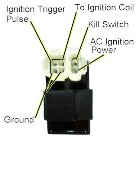
1) Unplug the CDI, and turn on the ignition. Do not crank the starter motor. Use a meter to measure the *DC* voltage on the pin labeled "AC ignition power" in the wiring harness to both ground pins in the 4 pin CDI connector. If you measure 12 volts DC then you have a DC powered CDI.
2) If you don't measure 12 volts DC on the ignition power pin, then switch the meter over to measure AC volts on the 200 volt scale. While cranking the starter motor, measure the AC voltage on the "AC Ignition Power" pin to the the Ground pin. You should see 40 to 80 volts AC. If you measure AC voltage when the starter is turning then you have an AC powered CDI.
Using a meter is the only 100% reliable way to figure out if your CDI is AC or DC powered. But there are some clues you can use that are usually (but not always) correct:
A) DC CDIs tend to be a little larger than their AC powered counterpart. This is because the DC powered CDI needs a bunch more circuitry to convert the 12 volts DC to the moderately high voltage supply that all CDIs must have.
B) Most (but not all) DC powered quad ignition systems do not use the kill switch input pin. The CDI connector pin usually has no wire tied to it. AC powered quad ignition systems usually do use the kill switch input pin.
Dec 20, 2011 | 04:17 PM
#3
Thread Starter
|
Weekend Warrior
Joined: Oct 2011
Posts: 10
Likes: 0
Thanks for the info... Since I orderd the CDI box directly from Jetmoto, it should be the correct one. However, I will check.
Additioanlly, since I forgot to mention that the inline fuse popped after trying to crank it, I figured there is a short coming from some where. I highly suspect the shut off switch, which is what I am going to check tonight. I ran across one of your other posts discussing pin placement of the 6 pin CDI box (like the one included) and printed that info out last night, but didn't get a chance to check it. Should be an easy check and something I can rule out quickly. If the shut off switch checks out I look to see if it is a AC or DC system. Then look for a stator. I will keep you posted.... Thanks Again!
Additioanlly, since I forgot to mention that the inline fuse popped after trying to crank it, I figured there is a short coming from some where. I highly suspect the shut off switch, which is what I am going to check tonight. I ran across one of your other posts discussing pin placement of the 6 pin CDI box (like the one included) and printed that info out last night, but didn't get a chance to check it. Should be an easy check and something I can rule out quickly. If the shut off switch checks out I look to see if it is a AC or DC system. Then look for a stator. I will keep you posted.... Thanks Again!
Dec 20, 2011 | 10:40 PM
#5
Electrical Expert
Likes High Voltage In The Tub!
Likes High Voltage In The Tub!
Joined: Dec 2008
Posts: 3,260
Likes: 14
From: Tracy, California, USA
I need more info on the fuse blowing. Does it blow every time you crank the engine? Or does it blow every time you turn on the ignition? Or did it just blow once? What is the value of that fuse? When you look at the blown fuse (assuming the fuse element is visible inside), is the fuse element vaporized with black flash marks on the inside walls of the fuse? Or is the fuse element only slightly broken with a very small gap separating the two sides of the fuse element? [I'm just fishing for as many clues as I can get...]
Here is the generic procedure for checking a DC powered 6 pin CDI ignition system:
Here is the generic procedure for checking a DC powered 6 pin CDI ignition system:
To troubleshoot no spark problems on a 6 pin DC powered CDI it makes sense to start in the middle (the CDI), measure as much as we can and branch out from there. For the CDI to do its thing it needs power, a trigger pulse, and it must not be inhibited via the kill switch input pin.
1) Unplug the CDI. Turn the ignition switch on. Set all kill switches the the "run" position. In the wiring harness, look to see if you have a wire on the kill switch pin. If you do, measure the resistance of the kill switch pin to the ground pin on the 20K ohm scale. It should read infinite ohms (same as when the meter leads are hanging free and not touching anything). It should not read zero ohms (shorted).
2) Leave the CDI unplugged, and the ignition switch in the "on" position. Use a meter to measure the DC voltage on the pin labeled "AC ignition power" in the wiring harness to the ground wire on the 2K ohm scale. You should read battery voltage (12 volts). What do you measure?
3) Leave the CDI unplugged. Use a meter to measure the resistance of the "Ignition Trigger Pulse" pin in the wiring harness to the ground wire on the 2K ohm scale. You should read approximately 150 ohms. What do you measure?
4) Set your meter down to the lowest scale you have for measuring AC volts. 2 volts would be ideal, but some meters don't go that low. In that case use the lowest scale you have. While cranking the engine, measure the voltage on the Ignition Trigger Pulse pin in the wiring harness to the ground pin. You should measure 0.2 to 0.5 volts AC. What do you measure?
5) Now plug the CDI back in. Measure the AC voltage on the Ignition Coil pin to the ground pin using the 200 volt scale. If you have to, use a sewing pin to poke through the wire insulation and then put the meter probe on the sewing pin. But don't hold your fingers on the connection during the next test - there may be high voltage here when the engine is turning. With the ignition on and all kill switches set to the "run" position, crank the starter motor. You should see voltages bouncing around at random values and the meter captures all or part of a spark event. What do you see?
Dec 21, 2011 | 10:31 AM
#6
Thread Starter
|
Weekend Warrior
Joined: Oct 2011
Posts: 10
Likes: 0
I will follow those instructions tonight on checking the specific values of the CDI/wiring harness and let you know what I find out. I do have a high dollar digital fluke meter, so I should be able to capture all of those values you discussed.
The blown fuse thing has only happened once. However, I have temporarily hard wired it until I get the problem fixed. Either one of two things will happen, 1: I let that magic smoke out of the wire and find exactly what is wrong then replace all the wiring... Or 2: nothing will happen because the fuse issue isn't related to the no spark problem.
The fuse is a 10 amp fuse and it was barely burned through. The glass was nice and clear. This is one reason I decided to temporarily hard wire it because I really didn't think it was related to the problem I was having, and I wanted to check and see if anything I was doing was working. But, I think I will pick up a box of 10 amp fuses tonight and see if they keep blowing or if it was a one time thing.
The blown fuse thing has only happened once. However, I have temporarily hard wired it until I get the problem fixed. Either one of two things will happen, 1: I let that magic smoke out of the wire
and find exactly what is wrong then replace all the wiring... Or 2: nothing will happen because the fuse issue isn't related to the no spark problem. The fuse is a 10 amp fuse and it was barely burned through. The glass was nice and clear. This is one reason I decided to temporarily hard wire it because I really didn't think it was related to the problem I was having, and I wanted to check and see if anything I was doing was working. But, I think I will pick up a box of 10 amp fuses tonight and see if they keep blowing or if it was a one time thing.
Dec 21, 2011 | 07:14 PM
#7
Thread Starter
|
Weekend Warrior
Joined: Oct 2011
Posts: 10
Likes: 0
Okay, I performed the test you recommended and here are the results.
1) Unplug the CDI. Turn the ignition switch on. Set all kill switches the the "run" position. In the wiring harness, look to see if you have a wire on the kill switch pin. If you do, measure the resistance of the kill switch pin to the ground pin on the 20K ohm scale. It should read infinite ohms (same as when the meter leads are hanging free and not touching anything). It should not read zero ohms (shorted).
No, there is no wire to the kill switch pin.
2) Leave the CDI unplugged, and the ignition switch in the "on" position. Use a meter to measure the DC voltage on the pin labeled "AC ignition power" in the wiring harness to the ground wire on the 2K ohm scale. You should read battery voltage (12 volts). What do you measure?
I measured 11.97 volts
3) Leave the CDI unplugged. Use a meter to measure the resistance of the "Ignition Trigger Pulse" pin in the wiring harness to the ground wire on the 2K ohm scale. You should read approximately 150 ohms. What do you measure?
I measured .7 - 1.0 Ohms depending on what ground wire I used.
4) Set your meter down to the lowest scale you have for measuring AC volts. 2 volts would be ideal, but some meters don't go that low. In that case use the lowest scale you have. While cranking the engine, measure the voltage on the Ignition Trigger Pulse pin in the wiring harness to the ground pin. You should measure 0.2 to 0.5 volts AC. What do you measure?
I measured .001 volts...
5) Now plug the CDI back in. Measure the AC voltage on the Ignition Coil pin to the ground pin using the 200 volt scale. If you have to, use a sewing pin to poke through the wire insulation and then put the meter probe on the sewing pin. But don't hold your fingers on the connection during the next test - there may be high voltage here when the engine is turning. With the ignition on and all kill switches set to the "run" position, crank the starter motor. You should see voltages bouncing around at random values and the meter captures all or part of a spark event. What do you see?
I measured this at the coil, by unpluging the wire that feeds power to the coil and grounding my ground to the frame, which came up with nearly nothing. Since Step 2 and 3 look like that is where the problem is, I am sure there isn't voltage going to the coil.
With the Ignition Trigger Pulse failing the test, what is the component that feeds this?
Thanks,
Jeff
Trending Topics
Dec 21, 2011 | 11:05 PM
#8
Electrical Expert
Likes High Voltage In The Tub!
Likes High Voltage In The Tub!
Joined: Dec 2008
Posts: 3,260
Likes: 14
From: Tracy, California, USA
The resistance and voltage measured on the trigger pulse is definately wrong. But be careful - the resistance you measured sounds an awful lot like the resistance you would expect at the ignition coil output pin. These two pins are side by side, and note that the CDI picture and the connector face you're looking at will be mirror images of each other - because you have to flip the connector over to look at it after unplugging it from the CDI. Many people make this mistake. I just want to make sure you were actually measuring the right pin in the harness... 
If you really were measuring the right pin, then what color is that wire? Look down around the stator wires coming out of the engine. Find a wire that ties into the same color wire in the wiring harness. These two wires should be one and the same.
Unplug that wire from the stator and measure the resistance of the wire looking into the stator to ground. Is it still shorted (one ohm or less)? On some quads there are two ignition kill schemes, and one of them involves using a kill switch to short the ignition trigger signal to ground (which is completely separate from the kill switch pin on the CDI). By disconnecting the stator from the wire harness any such kill switches would also be disconnected, and you should measure 150 ohms or so to ground through the stator trigger winding. This will separate problems inside the stator from problems in the wiring outside the stator... Divide and conquer.
BTW, you must not measure the voltage on the coil primary with the coil disconnected (unplugged). Any results measured that way are completely meaningless. The CDI charges the internal storage capacitor through the low resistance of the ignition coil primary winding. You must have the coil hooked up or nothing inside the CDI will work at all.
If you really were measuring the right pin, then what color is that wire? Look down around the stator wires coming out of the engine. Find a wire that ties into the same color wire in the wiring harness. These two wires should be one and the same.
Unplug that wire from the stator and measure the resistance of the wire looking into the stator to ground. Is it still shorted (one ohm or less)? On some quads there are two ignition kill schemes, and one of them involves using a kill switch to short the ignition trigger signal to ground (which is completely separate from the kill switch pin on the CDI). By disconnecting the stator from the wire harness any such kill switches would also be disconnected, and you should measure 150 ohms or so to ground through the stator trigger winding. This will separate problems inside the stator from problems in the wiring outside the stator... Divide and conquer
.BTW, you must not measure the voltage on the coil primary with the coil disconnected (unplugged). Any results measured that way are completely meaningless. The CDI charges the internal storage capacitor through the low resistance of the ignition coil primary winding. You must have the coil hooked up or nothing inside the CDI will work at all.
Dec 23, 2011 | 09:39 AM
#9

Trailblazer
Joined: Oct 2007
Posts: 69
Likes: 0
One small thought on measuring the ignition trigger pulse....while Lynn was helping me troubleshoot mine, I was not able to pick up the voltage on my high dollar Amprobe digital meter (scan time is too slow). I picked up a cheap analog (swing needle) and was able to watch the pulse in real time as I cranked it. This is a small but important detail when trying to rule out pulse signal. I would have assumed my stator was toast. Hope this helped some and best of luck...
Denny
Denny
Dec 26, 2011 | 11:44 AM
#10
Electrical Expert
Likes High Voltage In The Tub!
Likes High Voltage In The Tub!
Joined: Dec 2008
Posts: 3,260
Likes: 14
From: Tracy, California, USA