
Long Chang Hurricane 125

 Jun 1, 2012 | 11:09 PM
#2

Electrical Expert
Likes High Voltage In The Tub!
Likes High Voltage In The Tub!
Joined: Dec 2008
Posts: 3,260
Likes: 14
From: Tracy, California, USA
I've never heard of that brand quad, but there are zillions of brands out there (many out of business now). But at the same time most of these quads are made with the same oem parts which are often interchangable with other brands.
I doubt there is any service manual.
No spark problems are pretty generic. First thing to identify: How many pins on your CDI? Four, five, or six pins? The six pin CDI's will have two connectors - a 2 pin and a 4 pin.
The troubleshooting procedure for "no spark" is different depending on which CDI you have.
Jun 2, 2012 | 07:06 AM
#3

Thread Starter
|
Weekend Warrior
Joined: Jun 2012
Posts: 9
Likes: 0
Thanks, i have a 6 pin CDI, i get 57.3 V AC when cranking on the AC ignition power pin on the CDI. by the way i have 2 wires going to the coil. red and white and black and white. on the coil there is a green tag. which way do the wires go? will it damage the coil if i put the wires on the wron way round?
Do you have a generic chinese quad bike circuit diagram?
Do you have a generic chinese quad bike circuit diagram?
Jun 2, 2012 | 09:53 AM
#4
Thread Starter
|
Weekend Warrior
Joined: Jun 2012
Posts: 9
Likes: 0
i get 8 VAC at the primary winding to the coil. still no spark.
A bit of back ground info, regarding the starting issue, the quad just stopped while at idle speed. it was running lumpy then it was fine then after about 5 mins it cut out. any help would be appreciated.
Thanks
Jed
A bit of back ground info, regarding the starting issue, the quad just stopped while at idle speed. it was running lumpy then it was fine then after about 5 mins it cut out. any help would be appreciated.
Thanks
Jed
Jun 2, 2012 | 10:47 PM
#5
Electrical Expert
Likes High Voltage In The Tub!
Likes High Voltage In The Tub!
Joined: Dec 2008
Posts: 3,260
Likes: 14
From: Tracy, California, USA
Thanks, i have a 6 pin CDI, i get 57.3 V AC when cranking on the AC ignition power pin on the CDI. by the way i have 2 wires going to the coil. red and white and black and white. on the coil there is a green tag. which way do the wires go? will it damage the coil if i put the wires on the wron way round?
Do you have a generic chinese quad bike circuit diagram?
Do you have a generic chinese quad bike circuit diagram?
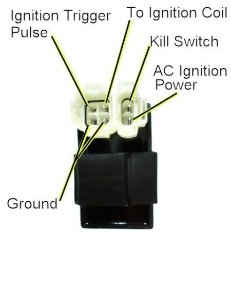
Look at the following picture and report back the colors for each function (i.e. ground, trigger, ignition powr, etc):

You won't hurt anything in the short term by wiring upthe coil backwards. If it doesn't work one way, then try the other. On the green tab I suspect that will be ground. Hopefully the wire colors at the CDI will help ID what wire color is used for ground on your quad.
There isn't a "generic" wiring diagram. That is because there are a few ways to wire up the starter interlock circuitry. There are a few ways to wire up the ingition system. There are a few ways to wire up the battery charging system. And there are a few ways to wire up lighting. So even though each of these local systems can only be hooked up a few ways, in total, considereing that all the systems can vary, you have a lot of possibilities. Thus the best plan is to concentrate on the system that isn't working (the ignition system in your case), and ignore the rest. Then we only have a few possibilities to iron out. A few measurements later we have that uncertaintly nailed down and then can concentrate on the actual problem.
Jun 2, 2012 | 10:55 PM
#6
Electrical Expert
Likes High Voltage In The Tub!
Likes High Voltage In The Tub!
Joined: Dec 2008
Posts: 3,260
Likes: 14
From: Tracy, California, USA
i get 8 VAC at the primary winding to the coil. still no spark.
A bit of back ground info, regarding the starting issue, the quad just stopped while at idle speed. it was running lumpy then it was fine then after about 5 mins it cut out. any help would be appreciated.
Thanks
Jed
A bit of back ground info, regarding the starting issue, the quad just stopped while at idle speed. it was running lumpy then it was fine then after about 5 mins it cut out. any help would be appreciated.
Thanks
Jed
Your measurements have already established that you have an AC powered CDI. SO let's go through the whole diagnostic procedure. Please do all the tests and provide precise answers from your written notes. Measurement error is commonplace - even with experienced tech's - so make sure the results you measure are repeatable. These tests are somewhat cross checking - values from one test can be used to check the believability of another:
To troubleshoot no spark problems on a 6 pin AC powered CDI it makes sense to start in the middle (the CDI), measure as much as we can and branch out from there. For the CDI to do its thing it needs power, a trigger pulse, and it must must be inhibited via the kill switch input pin.
1) Unplug the CDI. Turn the ignition switch on. Set all kill switches the the "run" position. In the wiring harness, measure the resistance of the kill switch pin to the ground pin on the 20K ohm scale. It should read infinite ohms (same as when the meter leads are hanging free and not touching anything). It should not read zero ohms (shorted).
2) Leave the CDI unplugged. Use a meter to measure the resistance of the AC ignition power pin in the wiring harness to the ground wire on the 2K ohm scale. You should read approximately 400 ohms. What do you measure?
3) In a similar fashion measure the resistance of the Ignition Trigger Pulse pin to the ground pin. You should see 150 ohms or so. What do you measure?
4) Switch your meter over to measure AC volts on the 200 volt scale. Leave the CDI unplugged. While cranking the engine, measure the voltage on the AC Ignition Power pin in the wiring harness to the ground pin. You should measure 40 to 80 volts AC. What do you measure?
5) Set your meter down to the lowest scale you have for measuring AC volts. 2 volts would be ideal, but some meters don't go that low. In that case use the lowest scale you have. While cranking the engine, measure the voltage on the Ignition Trigger Pulse pin in the wiring harness to the ground pin. You should measure 0.2 to 0.5 volts AC. What do you measure?
6) Now plug the CDI back in. Measure the AC voltage on the Ignition Coil pin to the ground pin using the 200 volt scale. If you have to, use a sewing pin to poke through the wire insulation and then put the meter probe on the sewing pin. But don't hold your fingers on the connection during the next test - there may be high voltage here when the engine is turning. With the ignition on and all kill switches set to the "run" position, crank the starter motor. You should see voltages bouncing around at random values and the meter captures all or part of a spark event. What do you see?
Jun 3, 2012 | 08:15 AM
#7
Thread Starter
|
Weekend Warrior
Joined: Jun 2012
Posts: 9
Likes: 0
Thanks LynnEdwards,
measurements were
1. Infinity
2. 467 Ohms
3. 146 Ohms
4. 52 V AC
5 0.35 V AC
6. 6.5 V AC
Wire colours on CDI unit are
4 Pin Plug
Ignition Trigger Pulse - Blue & White
To Ignition Coil - Red & White
Ground x2 - Black & White
2 Pin Plug
Kill Switch - Red & Black
AC Ignition Power - Black & White
From the engine block Blue & White & Red & White both bullet connectors and a 4 pin connector only 3 pins used - Green, White, Yellow. The green then changes colour to black & White on the male side of the connector. other colours remain the same.
I hope this helps, i look forward to your reply.
Cheers Jed
Trending Topics
Jun 3, 2012 | 08:36 PM
#8
Electrical Expert
Likes High Voltage In The Tub!
Likes High Voltage In The Tub!
Joined: Dec 2008
Posts: 3,260
Likes: 14
From: Tracy, California, USA
All your measurments above are reasonable. It kind of suggests that your CDI output is OK. That leaves the ignition coil and the spark plug. I'd start with the spark plug since it is the easiest and the cheapest. Then the ignition coil is next. It is always possible that there is a problem with the CDI that is producing voltage but not the right waveform. This is much less likely then coil or plug problems however. The CDI output should be measured with an oscilloscope for absolute accuracy, but this is impractical for most people. So we use a meter, accept its limitations, and make the best educated guess from there. Fortunately chinese parts are inexpensive, so there isn't a big risk with the educated guess...
Thanks LynnEdwards,
....Wire colours on CDI unit are
4 Pin Plug
Ignition Trigger Pulse - Blue & White
To Ignition Coil - Red & White
Ground x2 - Black & White
2 Pin Plug
Kill Switch - Red & Black
AC Ignition Power - Black & White
From the engine block Blue & White & Red & White both bullet connectors and a 4 pin connector only 3 pins used - Green, White, Yellow. The green then changes colour to black & White on the male side of the connector. other colours remain the same....
Jun 4, 2012 | 06:59 AM
#9
Thread Starter
|
Weekend Warrior
Joined: Jun 2012
Posts: 9
Likes: 0
Thanks, i have access to an Oscilloscope, what wave form should i see. the thing that puzzles me is the voltage at the primary of the coil. to me it seems low, what voltage should i see here. the spark plug was changed recently with a NGK. i will buy a CDI unit and see what happens, the coil pack is cheap too so i will probably change that also. i will post the results when i get the new parts.
Thanks again.
Jed
Thanks again.
Jed
Jun 5, 2012 | 12:03 AM
#10
Electrical Expert
Likes High Voltage In The Tub!
Likes High Voltage In The Tub!
Joined: Dec 2008
Posts: 3,260
Likes: 14
From: Tracy, California, USA
This is what you should see at the CDI output for the generic common chinese CDI:

Since CDI's are just black boxes that take power and trigger signals and make semi high voltage pulses, it is possible that there are other CDI designs with different waveforms. But the above is very common.
Since CDI's are just black boxes that take power and trigger signals and make semi high voltage pulses, it is possible that there are other CDI designs with different waveforms. But the above is very common.

