
125 taotao start problems
 Oct 19, 2012 | 08:25 PM
#1

Thread Starter
|
Trailblazer
Joined: Oct 2012
Posts: 45
Likes: 0
From: Dungannon Ont Canada
Working on a Taotao 125 with a 3 speed with reverse, manual shift ,auto clutch , just not sure of the exact model. I have no spark. New stator, coil, cdi. I am not so sure the new stator is any good and cannot find the proper readings for the stator and a wiring diagram would be great. I checked the taotao library but could only find specs for the 110. Are they the same? Seem to be a decentmachine except for this POS. Driving me around the bend and the owner is not impressed. thanks in advance.
Oct 19, 2012 | 11:45 PM
#2

Electrical Expert
Likes High Voltage In The Tub!
Likes High Voltage In The Tub!
Joined: Dec 2008
Posts: 3,260
Likes: 14
From: Tracy, California, USA
Do you have a five pin CDI or a four pin CDI? The first is AC powered from the stator, and the second is DC powered off the 12 volt power bus. The testing procedures are different for the two.
What is the "Tao Tao Library". I would like to take a look if it isn't proprietary. Tao Tao has been one of the worst companies for providing documentation of what they sell.
What is the "Tao Tao Library". I would like to take a look if it isn't proprietary. Tao Tao has been one of the worst companies for providing documentation of what they sell.
Oct 20, 2012 | 07:53 AM
#3
Thread Starter
|
Trailblazer
Joined: Oct 2012
Posts: 45
Likes: 0
From: Dungannon Ont Canada
go to Taotao Canada and click on support. The heading for library comes up. click on that and itopens the door to different manuals. The 125 and 110 come under the same heading so I'm wondering if the readins are the same although the cdi are different. I do believe there are 7 pins on the cdi but I will have to check.
Oct 20, 2012 | 09:32 PM
#4
Electrical Expert
Likes High Voltage In The Tub!
Likes High Voltage In The Tub!
Joined: Dec 2008
Posts: 3,260
Likes: 14
From: Tracy, California, USA
go to Taotao Canada and click on support. The heading for library comes up. click on that and itopens the door to different manuals. The 125 and 110 come under the same heading so I'm wondering if the readins are the same although the cdi are different. I do believe there are 7 pins on the cdi but I will have to check.
Their troubleshooting procedures suck big time. OMG, are they bad
 . Life's like that. You take the good with the bad, and then throw out the bad. Ignore their troubleshooting procedures - they have no clue...
Still waiting on your CDI pin count. I really doubt you have a 7 pin CDI...
Oct 21, 2012 | 08:38 PM
#6
Electrical Expert
Likes High Voltage In The Tub!
Likes High Voltage In The Tub!
Joined: Dec 2008
Posts: 3,260
Likes: 14
From: Tracy, California, USA
Standard procedure for troubleshooting an AC powered 5 pin CDI:
Add step where any remote module is disconnected for all no spark tests...
Add step where any remote module is disconnected for all no spark tests...
Is this a picture of your CDI?
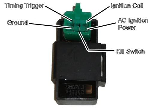
Assuming the answer is yes, the first thing to do is eliminate all kill switches and kill switch wiring:
Method 1) Unplug the CDI and remove the kill switch pin in the CDI connector on the wiring harness. The pin is held in with a spring tab on the pin itself. You'll have to probe into the connector and push this tab in order to extract the pin. Plug the CDI back in (kill switch wire dangling) and see if you have spark.
Method 2) Unplug the CDI. Turn on the ignition switch and set all kill switches to the run position. Use a meter to measure resistance in of the kill switch pin in the wiring harness connector to engine/frame ground. If the resistance is infinite on the 200K ohm scale then your kill switches/kill switch wiring are OK. If you measure zero ohms then you have a kill switch/wiring issue.
The other inputs your CDI needs to make spark are AC Ignition Power, and the Trigger signal. Do the following:
1) Unplug the CDI. In the wiring connector measure the resistance of the AC Ignition Power pin to the Ground pin. You should see 400 ohms or so. What do you measure?
2) Measure the resistance of the Timing/trigger pin to the ground pin. You should measure 150 ohms or so. What do you measure?
3) Leave the CDI unplugged. Set your meter to measure AC volts on the 100 volt scale. Measure the voltage on the AC Ignition Power pin to the ground pin while cranking the engine. You should see 40 to 80 volts AC while the engine is cranking. What do you measure?
4) Set your meter to measure AC volts on the lowest scale you have. Ideally this would be 2 volts but many meters don't go down this low. In that case use the lowest scale you have. Measure the voltage on the Timing Trigger pin to the Ground pin while cranking the engine. You should 0.2 t0 0.4 volts AC. What do you measure?
Now for measuring the output side of the CDI:
A) Leave the CDI unplugged. In the CDI wiring connector measure the resistance of the Ignition Coil pin to the ground pin. You should measure less than 1 ohm (but not zero ohms). What do you measure?
B) Plug the CDI back in. Set your meter to measure AC volts on the 20 volt scale. Set all kill switches to the run position. Crank the engine while measuring the voltage on the Igntition Coil pin to ground. Poke through the insulation of the wire if you can't probe the connector.
Caution: There should be moderately high voltage spikes on this wire. Make sure your fingers are not part of the circuitry. Don't touch the probe lead tips while doing this test.
What you should see is a lot of random numbers with lots of zero values as well. This is because the meter may catch all or part of the spark event voltage, with a lot of nothing in between. Describe what you see.
Note: Using a meter to measure this point produces highly variable results depending on the meter. What you really need is an oscilloscope, but most always a meter is all that is available. We have to do the best we can with what's available. Describe the meter results as accurately as you can - there is information there to chew on....

Thread
Thread Starter
Forum
Replies
Last Post
Currently Active Users Viewing This Thread: 1 (0 members and 1 guests)