
aussie john
 Oct 31, 2012 | 10:05 PM
#2

Electrical Expert
Likes High Voltage In The Tub!
Likes High Voltage In The Tub!
Joined: Dec 2008
Posts: 3,260
Likes: 14
From: Tracy, California, USA
I've never heard of your quad. That's not surprising though considering how many "me too" chinese brands are out there.
How exactly did you do the "no spark" test?
What size engine?
How many pins on your CDI?
How exactly did you do the "no spark" test?
What size engine?
How many pins on your CDI?
Nov 1, 2012 | 02:20 AM
#3

Thread Starter
|
Weekend Warrior
Joined: Oct 2012
Posts: 5
Likes: 0
hi lynn the chinese quad is a air cooled 250 i pulled the spark plug out earthing it and turning the motor over.it had a switch on the clutch lever which i had to replace but the new one has not got one on.the cdi has 2 plugs on it one has 4 wires the other 2.the 4 wires are 2 green 1 black/yellow and the other blue/white .the other plug has a black/red and black/white .hope you can help i am trying to get it going for my grandkids thanks again 
Nov 2, 2012 | 11:01 PM
#4
Electrical Expert
Likes High Voltage In The Tub!
Likes High Voltage In The Tub!
Joined: Dec 2008
Posts: 3,260
Likes: 14
From: Tracy, California, USA
There are two kinds of 6 pin CDIs like yours, and unfortunately they look identical. So the first step is to determine if you have a DC powerd CDI, or an AC powered CDI. Here is the generic procedure for determining that:
Once you've figured out which version CDI you have I can post the next set of tests based on your CDI (the're quite different).
The 2 plug 6 wire CDIs come in two different designs. One is powered off 12 volts DC, and the other is powered off a moderately high voltage AC which comes from the stator. Unfortunately there is no reliable way to tell the difference between the two by just looking at them. To be sure you need to use a meter to find out which you have:
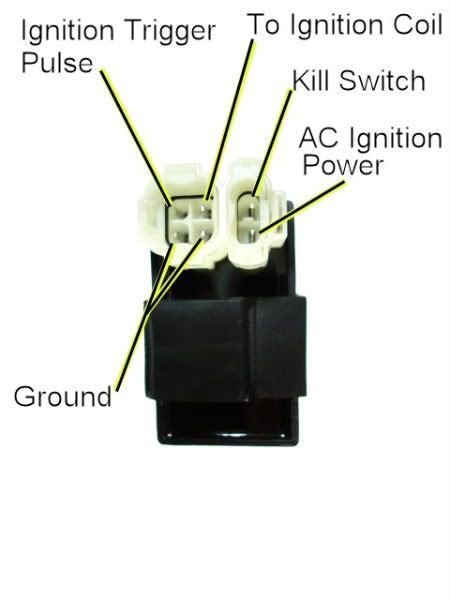
1) Unplug the CDI, and turn on the ignition. Do not crank the starter motor. Use a meter to measure the *DC* voltage on the pin labeled "AC ignition power" in the wiring harness to both ground pins in the 4 pin CDI connector. If you measure 12 volts DC then you have a DC powered CDI.
2) If you don't measure 12 volts DC on the ignition power pin, then switch the meter over to measure AC volts on the 200 volt scale. While cranking the starter motor, measure the AC voltage on the "AC Ignition Power" pin to the the Ground pin. You should see 40 to 80 volts AC. If you measure AC voltage when the starter is turning then you have an AC powered CDI.
Using a meter is the only 100% reliable way to figure out if your CDI is AC or DC powered. But there are some clues you can use that are usually (but not always) correct:
A) DC CDIs tend to be a little larger than their AC powered counterpart. This is because the DC powered CDI needs a bunch more circuitry to convert the 12 volts DC to the moderately high voltage supply that all CDIs must have.
B) Most (but not all) DC powered quad ignition systems do not use the kill switch input pin. The CDI connector pin usually has no wire tied to it. AC powered quad ignition systems usually do use the kill switch input pin.
Nov 2, 2012 | 11:11 PM
#5
Electrical Expert
Likes High Voltage In The Tub!
Likes High Voltage In The Tub!
Joined: Dec 2008
Posts: 3,260
Likes: 14
From: Tracy, California, USA
I don't know why the image in my last post isn't loading. Here it is uploaded directly (click or hover over the thumbnail for a larger image):

This is the second picture from photobucket that won't download now, yet the link I used to upload to atvconnection is identical. Very strange...

This is the second picture from photobucket that won't download now, yet the link I used to upload to atvconnection is identical. Very strange...
 Nov 6, 2012 | 11:34 PM
#7
Electrical Expert
Likes High Voltage In The Tub!
Likes High Voltage In The Tub!
Joined: Dec 2008
Posts: 3,260
Likes: 14
From: Tracy, California, USA
No readings on both? Please explain. Your meter was blank? Did you forget to turn it on? Of course your meter didn't display "nothing". One of the major problems I face is responses like "it all measured good", or "I got nothing" to complicated procedures. I never know if "nothing" means 'I got zero volts on that pin cranking on the 200 volts AC scale', or 'I have absolutely no clue as to what I am doing'. I have to ask the question...  .
.
Assuming you have no power to the CDI (AC or DC), then look down to the the stator wires coming out of the engine side cover. How many wires and what are the colors? Then (more importantly), follow those wires to the connector(s) into the main harness. Do you see a black/red wire in the main harness? Use your ohmmeter setting on the meter to see if this black/red wire is connected to the black/red wire at the CDI.
Do you have a black/red wire in the harness at the stator connector, and is it connected to a black/red wire at the CDI? If so your CDI is AC powered, and we can dig in from there. If you don't have a black/red wire at the stator connector(s) on the wiring harness side then we need to look at the possibility of a DC power CDI.
.Assuming you have no power to the CDI (AC or DC), then look down to the the stator wires coming out of the engine side cover. How many wires and what are the colors? Then (more importantly), follow those wires to the connector(s) into the main harness. Do you see a black/red wire in the main harness? Use your ohmmeter setting on the meter to see if this black/red wire is connected to the black/red wire at the CDI.
Do you have a black/red wire in the harness at the stator connector, and is it connected to a black/red wire at the CDI? If so your CDI is AC powered, and we can dig in from there. If you don't have a black/red wire at the stator connector(s) on the wiring harness side then we need to look at the possibility of a DC power CDI.
Trending Topics
Nov 8, 2012 | 02:48 AM
#8
Thread Starter
|
Weekend Warrior
Joined: Oct 2012
Posts: 5
Likes: 0
hi lynn i should have been a bit more spacific in my answer i have a multi meter with a digital readout and after doing both ac and dc tests the meter read 0.00 on both tests .there is a black and red wire at the stator and the cdi.after stripping back some of the casing on the wiring loom i have found some of the wires melted together so i will have rewire that part or try and get another loom.the cdi is not very big as well.
Nov 8, 2012 | 11:12 PM
#9
Electrical Expert
Likes High Voltage In The Tub!
Likes High Voltage In The Tub!
Joined: Dec 2008
Posts: 3,260
Likes: 14
From: Tracy, California, USA
If the black/red wire from the stator connector ohms out to the black/red wire at you CDI then you have an AC powered CDI.
Here is the generic AC powered 6 pin CDI procedure:
Here is the generic AC powered 6 pin CDI procedure:
To troubleshoot no spark problems on a 6 pin AC powered CDI it makes sense to start in the middle (the CDI), measure as much as we can and branch out from there. For the CDI to do its thing it needs power, a trigger pulse, and it must not be inhibited via the kill switch input pin.
1) Unplug the CDI. Turn the ignition switch on. Set all kill switches the the "run" position. In the wiring harness, measure the resistance of the kill switch pin to the ground pin on the 20K ohm scale. It should read infinite ohms (same as when the meter leads are hanging free and not touching anything). It should not read zero ohms (shorted).
2) Leave the CDI unplugged. Use a meter to measure the resistance of the AC ignition power pin in the wiring harness to the ground wire on the 2K ohm scale. You should read approximately 400 ohms. What do you measure?
3) In a similar fashion measure the resistance of the Ignition Trigger Pulse pin to the ground pin. You should see 150 ohms or so. What do you measure?
4) Switch your meter over to measure AC volts on the 200 volt scale. Leave the CDI unplugged. While cranking the engine, measure the voltage on the AC Ignition Power pin in the wiring harness to the ground pin. You should measure 40 to 80 volts AC. What do you measure?
5) Set your meter down to the lowest scale you have for measuring AC volts. 2 volts would be ideal, but some meters don't go that low. In that case use the lowest scale you have. While cranking the engine, measure the voltage on the Ignition Trigger Pulse pin in the wiring harness to the ground pin. You should measure 0.2 to 0.5 volts AC. What do you measure?
6) Now plug the CDI back in. Measure the AC voltage on the Ignition Coil pin to the ground pin using the 200 volt scale. If you have to, use a sewing pin to poke through the wire insulation and then put the meter probe on the sewing pin. But don't hold your fingers on the connection during the next test - there may be high voltage here when the engine is turning. With the ignition on and all kill switches set to the "run" position, crank the starter motor. You should see voltages bouncing around at random values and the meter captures all or part of a spark event. What do you see?

Thread
Thread Starter
Forum
Replies
Last Post
Currently Active Users Viewing This Thread: 1 (0 members and 1 guests)