
50cc no fire when hot
 Aug 9, 2011 | 03:46 PM
#1

Thread Starter
|
Trailblazer
Joined: Apr 2008
Posts: 72
Likes: 0
I have a 50 cc Giovanni atv which has a copy of the old honda 50cc engine. It works perfect for about 20 min. and then it quits and there is no fire at the plug. If I leave it for approx. 1/2 hour it will start up again and work fine for another 20-30 min. Is there some overheat protection system built into these or what could be the problem. Sometimes it works fine for longer periods but this has been happening for over a year now. I tried a new plug and the same thing happens. I have it geared down with larger rear sprocket and smaller front one but also have the throttle limited to approx. half of normal travel. Thanks for any help.
Aug 9, 2011 | 09:09 PM
#2

Electrical Expert
Likes High Voltage In The Tub!
Likes High Voltage In The Tub!
Joined: Dec 2008
Posts: 3,260
Likes: 14
From: Tracy, California, USA
Is your CDI a four pin CDI or a five pin?
Assuming you have the more common 5 pin, here is the generic procedure for troubleshooting ignition system troubles. If you have a four pin CDI we will need to use a different procedure.
The fact that you have such long warmup and cool down times points to the stator because it is so thermally massive - and therefore must necessarally have long warm/cool times. Components such as the CDI and coil would cool very quickly (and they don't heat up much anyway). So when doing the measurements below pay particular attention to AC Igniton power pin tests and the Timing Trigger tests. But do them all just to cover all bases .
.
Assuming you have the more common 5 pin, here is the generic procedure for troubleshooting ignition system troubles. If you have a four pin CDI we will need to use a different procedure.
The fact that you have such long warmup and cool down times points to the stator because it is so thermally massive - and therefore must necessarally have long warm/cool times. Components such as the CDI and coil would cool very quickly (and they don't heat up much anyway). So when doing the measurements below pay particular attention to AC Igniton power pin tests and the Timing Trigger tests. But do them all just to cover all bases
.
Is this a picture of your CDI?
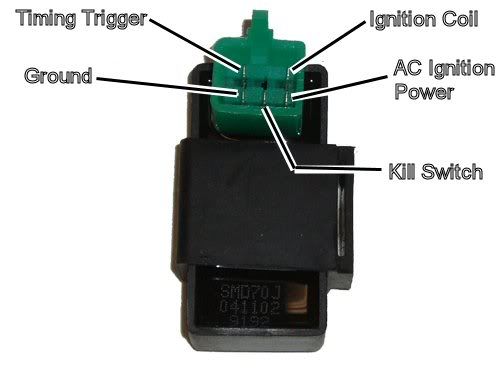
Assuming the answer is yes, the first thing to do is eliminate all kill switches abd kill switch wiring:
Method 1) Unplug the CDI and remove the kill switch pin in the CDI connector on the wiring harness. The pin is held in with a spring tab on the pin itself. You'll have to probe into the connector and push this tab in order to extract the pin. Plug the CDI back in (kill switch wire dangling) and see if you have spark.
Method 2) Unplug the CDI. Turn on the ignition switch and set all kill switches to the run position. Use a meter to measure resistance in of the kill switch pin in the wiring harness connector to engine/frame ground. If the reistance is infinite on the 100K ohm scale then your kill switches/kill switch wiring are OK. If you measure zero ohms then you have a kill switch/wiring issue.
The other inputs your CDI needs to make spark are AC Ignition Power, and the Trigger signal. Do the following:
1) Unplug the CDI. In the wiring connector measure the resistance of the AC Ignition Power pin to the Ground pin. You should see 400 ohms or so. What do you measure?
2) Measure the resistance of the Timing/trigger pin to the ground pin. You should measure 150 ohms or so. What do you measure?
3) Leave the CDI unplugged. Set your meter to measure AC volts on the 100 volt scale. Measure the voltage on the AC Ignition Power pin to the ground pin while cranking the engine. You should see 40 to 80 volts AC while the engine is cranking. What do you measure?
4) Set your meter to measure AC volts on the lowest scale you have. Ideally this would be 2 volts but many meters don't go down this low. In that case use the lowest scale you have. Measure the voltage on the Timing Trigger pin to the Ground pin while cranking the engine. You should 0.2 t0 0.4 volts AC. What do you measure?
Now for measuring the output side of the CDI:
A) Leave the CDI unplugged. In the CDI wiring connector measure the resistance of the Ignition Coil pin to the ground pin. You should measure less than 1 ohm (but not zero ohms). What do you measure?
B) Plug the CDI back in. Set your meter to measure AC volts on the 20 volt scale. Set all kill switches to the run position. Crank the engine while measuring the voltage on the Igntition Coil pin to ground. Poke through the insulation of the wire if you can't probe the connector.
Caution: There should be moderately high voltage spikes on this wire. Make sure your fingers are not part of the circuitry. Don't touch the probe lead tips while doing this test.
What you should see is a lot of random numbers with lots of zero values as well. This is because the meter may catch all or part of the spark event voltage, with a lot of nothing in between. Describe what you see.
Note: Using a meter to measure this point produces highly variable results depending on the meter. What you really need is an oscilloscope, but most always a meter is all that is available. We have to do the best we can with what's available. Describe the meter results as accurately as you can - there is information there to chew on....
Aug 9, 2011 | 11:25 PM
#3
Electrical Expert
Likes High Voltage In The Tub!
Likes High Voltage In The Tub!
Joined: Dec 2008
Posts: 3,260
Likes: 14
From: Tracy, California, USA
I forgot in my last post one of the most important things:
Since your problem is intermittent you must do these tests while the quad is *not* producing spark - i.e. the quad is malfunctioning. If you do these test while the quad is getting spark you will only prove that the quad is working fine which is not helpful at all.
Intermittent problems are more difficult to nail down than just flat dead problems. You need to bracket all diagnostic tests with "spark not present" tests to make sure you don't get erroneous and misleading results. In other words, check for spark and verify you don't have it. Then do a few tests to test the ignition system components per the above procedure and record the results. Then check for spark again to make sure you *still* don't have spark. If now you do have spark then any logged results are invalid and must be disregarded.
Aug 10, 2011 | 04:40 AM
#4
Thread Starter
|
Trailblazer
Joined: Apr 2008
Posts: 72
Likes: 0
Thanks so much for your help, I will measure all these voltages and post back. One more thing, I went to the manufacturers website
The Definitive ATV Starting Guide: Troubleshooting and More | GIO
and they have an ignition troubleshouting guide. They talk about a small metal fined voltage regulator that could give these symptoms if it is not dissipating heat fast enough. The guide is for all their ATV's so I don't know if my little 50 would have one, what do you think?
Aug 10, 2011 | 10:59 PM
#5
Electrical Expert
Likes High Voltage In The Tub!
Likes High Voltage In The Tub!
Joined: Dec 2008
Posts: 3,260
Likes: 14
From: Tracy, California, USA
Thanks so much for your help, I will measure all these voltages and post back. One more thing, I went to the manufacturers website
The Definitive ATV Starting Guide: Troubleshooting and More | GIO
and they have an ignition troubleshouting guide. They talk about a small metal fined voltage regulator that could give these symptoms if it is not dissipating heat fast enough. The guide is for all their ATV's so I don't know if my little 50 would have one, what do you think?
The Definitive ATV Starting Guide: Troubleshooting and More | GIO
and they have an ignition troubleshouting guide. They talk about a small metal fined voltage regulator that could give these symptoms if it is not dissipating heat fast enough. The guide is for all their ATV's so I don't know if my little 50 would have one, what do you think?
Your 50cc quad does have a voltage regulator, but all that thing does is keep your quad battery charged up. So if it fails the battery will go dead eventually from repeated starter operations, or if you run around with headlights on (and your headlights are DC powered). If you have the five pin CDI as pictured above the ignition system runs completely on its own moderately high voltage AC supply from the stator. You don't need the regulator, or even the battery to keep the engine running. You could remove both and the engine will keep right on running. Even on a four pin CDI (which *is* powered off 12 volts), a bad regulator will not make the quad stall and then not start back up unless the battery is so dead that the starter motor won't turn anymore.
Aug 28, 2011 | 11:48 AM
#6
Thread Starter
|
Trailblazer
Joined: Apr 2008
Posts: 72
Likes: 0
I finally got a chance to do some testing.
1) Unplug the CDI. In the wiring connector measure the resistance of the AC Ignition Power pin to the Ground pin. You should see 400 ohms or so. What do you measure?
425 ohms
2) Measure the resistance of the Timing/trigger pin to the ground pin. You should measure 150 ohms or so. What do you measure?
72ohms
3) Leave the CDI unplugged. Set your meter to measure AC volts on the 100 volt scale. Measure the voltage on the AC Ignition Power pin to the ground pin while cranking the engine. You should see 40 to 80 volts AC while the engine is cranking. What do you measure?
47 Volts
4) Set your meter to measure AC volts on the lowest scale you have. Ideally this would be 2 volts but many meters don't go down this low. In that case use the lowest scale you have. Measure the voltage on the Timing Trigger pin to the Ground pin while cranking the engine. You should 0.2 t0 0.4 volts AC. What do you measure?
on the 200 volt scale it is 0.0 before turning over and then 0.1 while turning over, on the 2 volt scale it stays at 0.0 at rest and while cranking
Now for measuring the output side of the CDI:
A) Leave the CDI unplugged. In the CDI wiring connector measure the resistance of the Ignition Coil pin to the ground pin. You should measure less than 1 ohm (but not zero ohms). What do you measure?
0.9 ohms
B) Plug the CDI back in. Set your meter to measure AC volts on the 20 volt scale. Set all kill switches to the run position. Crank the engine while measuring the voltage on the Igntition Coil pin to ground. Poke through the insulation of the wire if you can't probe the connector.
I don't have a 20 volt scale but on 200 volt scale it shows
0.0 at rest and 0.0 while cranking but after I leave it for 1/2 hour and test it the machine starts and runs and it reads .7-.8 while running.
Aug 28, 2011 | 11:48 PM
#7
Electrical Expert
Likes High Voltage In The Tub!
Likes High Voltage In The Tub!
Joined: Dec 2008
Posts: 3,260
Likes: 14
From: Tracy, California, USA
My comments embedded in blue:
So what happens to the resistance and voltage measurements above for the timing trigger pin between being hot (as measured above), and when the engine is cold and in the condition where it will start up? If you see any major change in voltage or resistances here it would point to the stator trigger wire as the culprit
I finally got a chance to do some testing.
1) Unplug the CDI. In the wiring connector measure the resistance of the AC Ignition Power pin to the Ground pin. You should see 400 ohms or so. What do you measure?
425 ohms [Sounds OK]
2) Measure the resistance of the Timing/trigger pin to the ground pin. You should measure 150 ohms or so. What do you measure?
72ohms [Sounds lower than most stators, but it might be OK]
3) Leave the CDI unplugged. Set your meter to measure AC volts on the 100 volt scale. Measure the voltage on the AC Ignition Power pin to the ground pin while cranking the engine. You should see 40 to 80 volts AC while the engine is cranking. What do you measure?
47 Volts [This is OK]
4) Set your meter to measure AC volts on the lowest scale you have. Ideally this would be 2 volts but many meters don't go down this low. In that case use the lowest scale you have. Measure the voltage on the Timing Trigger pin to the Ground pin while cranking the engine. You should 0.2 t0 0.4 volts AC. What do you measure?
on the 200 volt scale it is 0.0 before turning over and then 0.1 while turning over, on the 2 volt scale it stays at 0.0 at rest and while cranking
[On the 200 volt scale you are looking at changes of just 1 LSD (least significant digit) between 0.0 and 0.1. On the 2 volt scale you are in a much more accurate range. I would trust the 2 volt scale reading more, and this is wrong. It looks like you are getting no trigger pulse from the pickup coil in the stator. If you can get access to another meter and verify the results it would add further support to the diagnosis.]
Now for measuring the output side of the CDI:
A) Leave the CDI unplugged. In the CDI wiring connector measure the resistance of the Ignition Coil pin to the ground pin. You should measure less than 1 ohm (but not zero ohms). What do you measure?
0.9 ohms [This is OK]
B) Plug the CDI back in. Set your meter to measure AC volts on the 20 volt scale. Set all kill switches to the run position. Crank the engine while measuring the voltage on the Igntition Coil pin to ground. Poke through the insulation of the wire if you can't probe the connector.
I don't have a 20 volt scale but on 200 volt scale it shows
0.0 at rest and 0.0 while cranking but after I leave it for 1/2 hour and test it the machine starts and runs and it reads .7-.8 while running. [This is interesting. 0.7 to 0.8 volts isn't what I measure on my meters, but this could be a difference in meter design. Meters aren't supposed to measure these kind of weird waveforms, so differenty designed and perfectly good meters could read different. What is interesting is the difference between when the ignition system is working and when it is not.]
Trending Topics
Aug 29, 2011 | 02:54 PM
#8
Thread Starter
|
Trailblazer
Joined: Apr 2008
Posts: 72
Likes: 0
I will post back when I get another chance to check those. I was speaking to a small engine mechanic and he mentioned something about the air gap in the stator and that when it heated up the metal might be expending just enough to make the gap too big. What do you think of this possibility?
Aug 29, 2011 | 11:51 PM
#9
Electrical Expert
Likes High Voltage In The Tub!
Likes High Voltage In The Tub!
Joined: Dec 2008
Posts: 3,260
Likes: 14
From: Tracy, California, USA
I will post back when I get another chance to check those. I was speaking to a small engine mechanic and he mentioned something about the air gap in the stator and that when it heated up the metal might be expending just enough to make the gap too big. What do you think of this possibility?
The voltage generated by this "close fly by" depends a great deal on the gap between the flywheel bump and the pickup coil. On some quads this is adjustable, and on others it is fixed. If the gap is too great, the voltage generated at starter cranking speeds will not be sufficient to trigger the CDI, you will not get spark, and the quad won't start.
Now for some important stuff: The voltage generated not only depends upon the gap, but also depends upon the speed at which the raised bump flys by the pickup coil. In fact it is a linear relationship - double the engine speed and the trigger output voltage doubles. It is called Farady Induction if you want to look it up (after Michael Farady from the late 1800's). BTW, this increase in trigger voltage based on engine speed is the mechanism that the CDI uses to calculate and apply the timing advance curve necessary for higher engine speeds.
The point is that after your quad starts up the engine never gets below idle speed, which is about 1700 to 2000 RPM. Cranking speed is 600 RPM. Therefore it does not make sense that the engine would die when warm because of a gap problem. At idle the trigger voltage would be 2.5 times the cranking voltage. If you can start it *ever* the problem would not be the trigger coil gap. Thermal expansion could change the trigger voltage by 1 or 2% - not 250%.
Aug 30, 2011 | 04:14 AM
#10
Thread Starter
|
Trailblazer
Joined: Apr 2008
Posts: 72
Likes: 0
I checked the timer pin in the cold condition, 125 ohms and 0.0 volts at rest, 0.1 while cranking again on the 200v scale. Previously I said i checked it on the 2 volts scale but I was mistaken, it was 200u which is the next lower setting to 200volts. At that setting it remains 0.0 cold and hot at rest and while cranking.