
Foreman 500 Output Shaft Replacement How To
 Aug 25, 2014 | 10:43 PM
#1
Thread Starter
|
Pro Rider
Joined: Aug 2010
Posts: 230
Likes: 0
I'm gonna tag this thread with Foreman 500 secondary gear reduction. Im doing that because on the 500s the secondary gear reduction is accomplished by changing the gear on the output shaft and the smaller gear directly above it. So this could be very useful for someone doing that procedure as well.
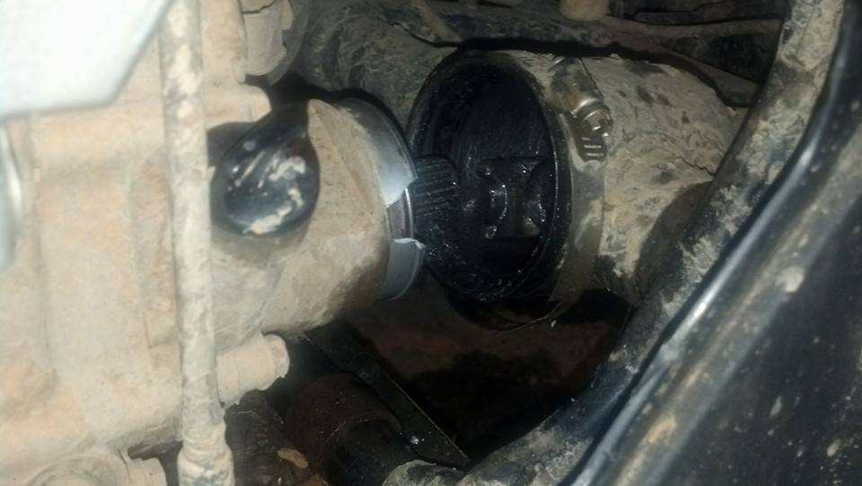
So let's start from the beginning. It was a great day to ride at Highlifter, and we set out into the woods. Not long after a heard a huge clunk and the bike lurched forward when giving it gas. I was able to engage 4wd and the front tires pulled me back to the trailer. There was some awful noises along the way however so I knew something was torn up pretty good. I cut the driveshaft boot off and found this:
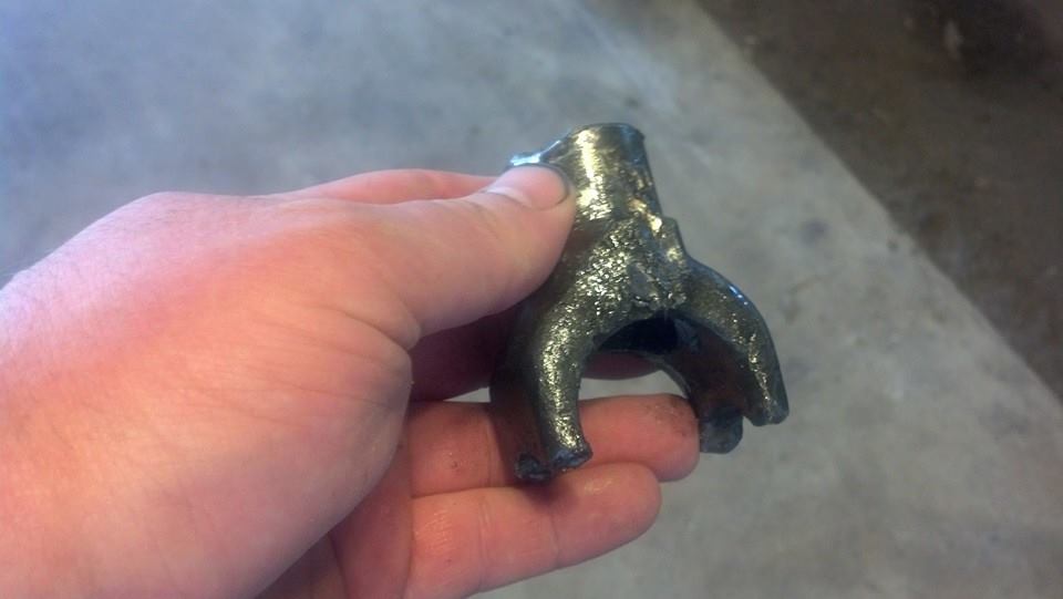
So I went ahead and took the swingarm off and this curious little guy fell out:
When I dumped the swingarm out, this was in the driveshaft tunnel:
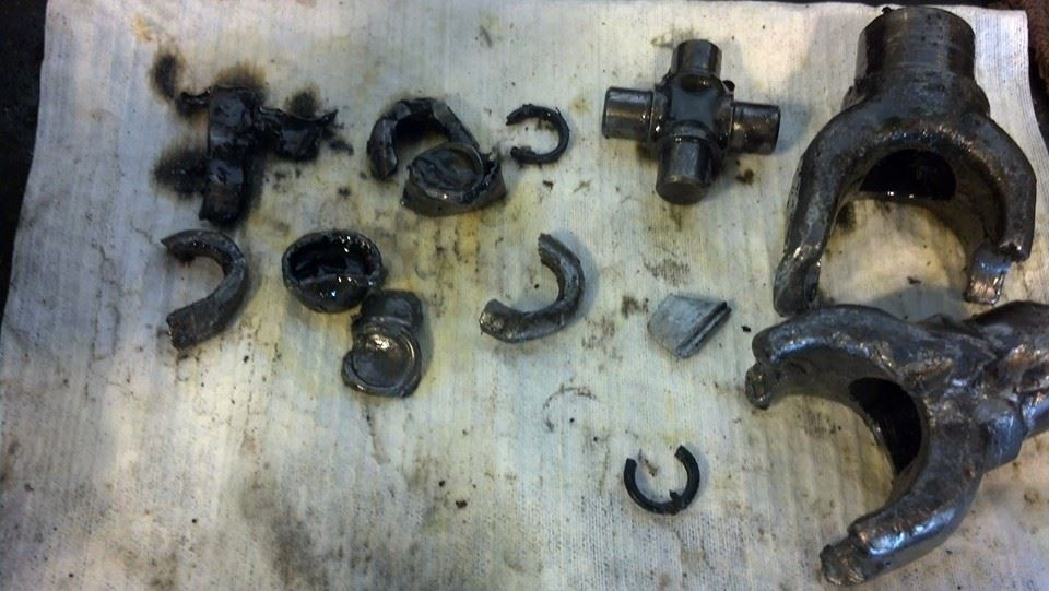
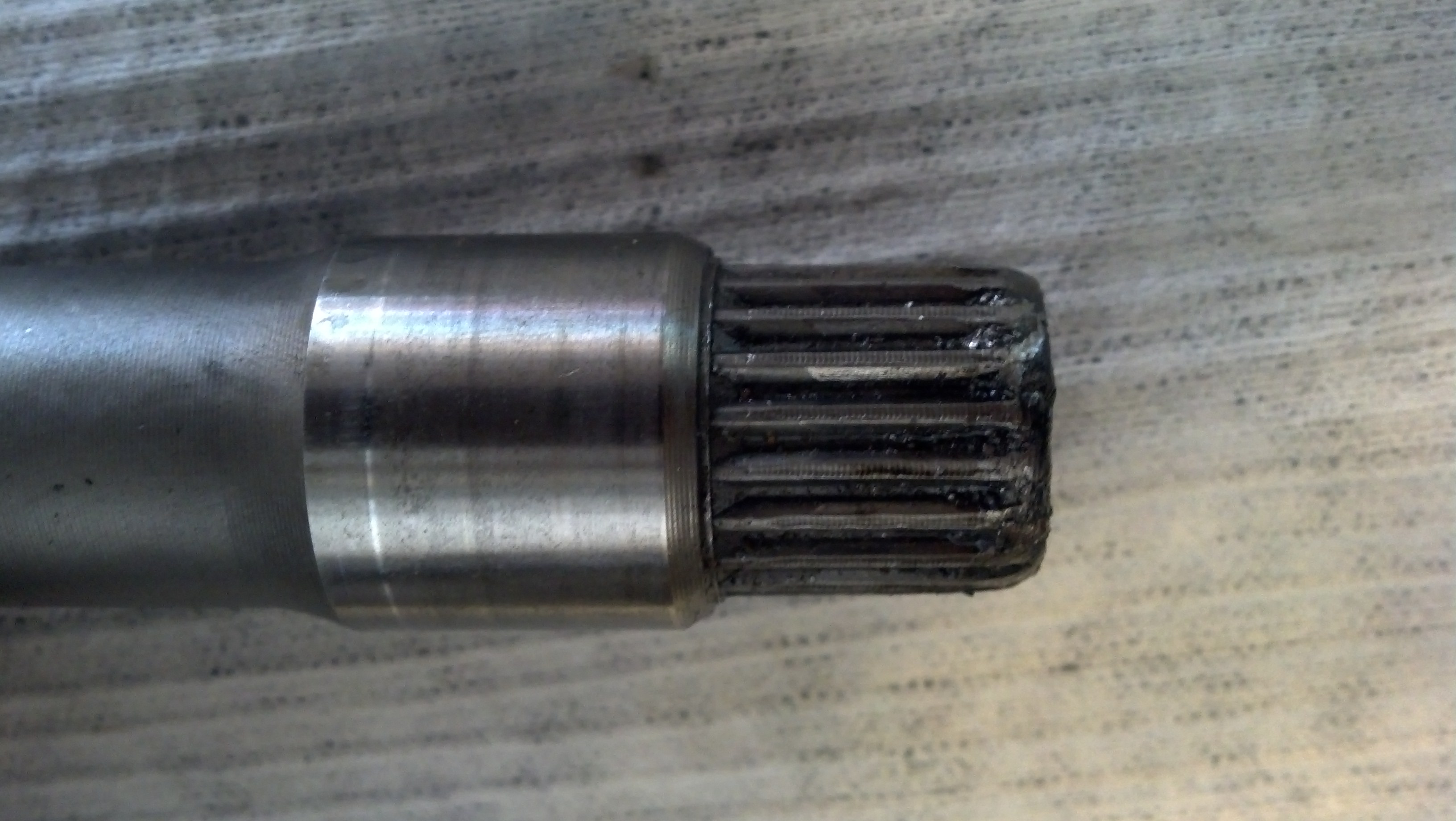
I also noticed the output shaft was bugared up, and the rear case was cracked a little, so I ordered up some parts.
Output shaft 23611-HP0-A00 $43
Rear crankcase cover 11340-HP0-A10 $136 (comes with 91201-965-000 o'ring pre-installed)
Kickstart cover gasket 11396-HP0-A00 $11
Rear cover gasket 11395-HP0-A00 $13
Output shaft seal 91205-HM7-003 $10
Optional but I did not order:
Kickstart oil seal 91202-HP0-A01 $8
--------------------
So let's start from the beginning. It was a great day to ride at Highlifter, and we set out into the woods. Not long after a heard a huge clunk and the bike lurched forward when giving it gas. I was able to engage 4wd and the front tires pulled me back to the trailer. There was some awful noises along the way however so I knew something was torn up pretty good. I cut the driveshaft boot off and found this:

So I went ahead and took the swingarm off and this curious little guy fell out:

When I dumped the swingarm out, this was in the driveshaft tunnel:

I also noticed the output shaft was bugared up, and the rear case was cracked a little, so I ordered up some parts.
Output shaft 23611-HP0-A00 $43
Rear crankcase cover 11340-HP0-A10 $136 (comes with 91201-965-000 o'ring pre-installed)
Kickstart cover gasket 11396-HP0-A00 $11
Rear cover gasket 11395-HP0-A00 $13
Output shaft seal 91205-HM7-003 $10
Optional but I did not order:
Kickstart oil seal 91202-HP0-A01 $8
--------------------
Aug 25, 2014 | 10:47 PM
#2
Thread Starter
|
Pro Rider
Joined: Aug 2010
Posts: 230
Likes: 0
Ok so I propped it up, swingarm already removed, to get ready for teardown: Note its no longer sitting
on the rear jackstands because I hooked a chain hoist to the rear and lifted it by the rafters.
Made it much easier to roll under with my stool.
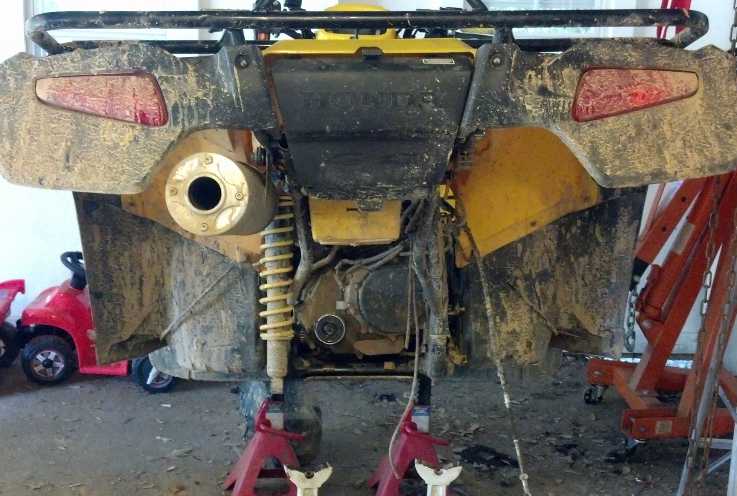
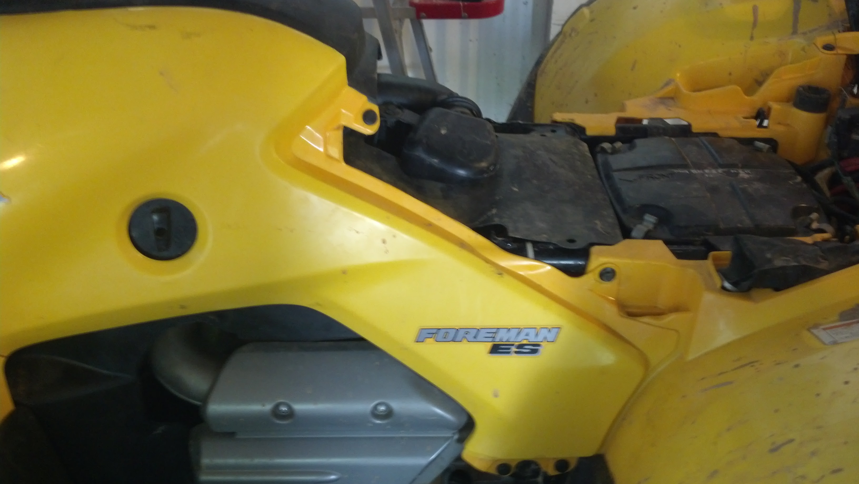
This is pretty basic. Pull the driver's side tank plastic off, oil fill cover, and complete airbox
assembly. That's basically it, you can see the entire rear of the engine once that is removed.
Make sure you have all the right parts:
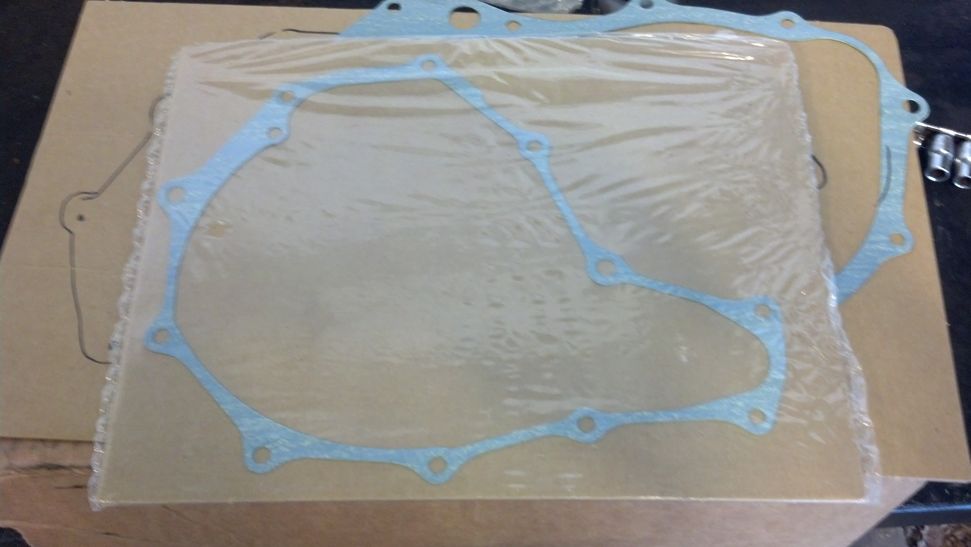
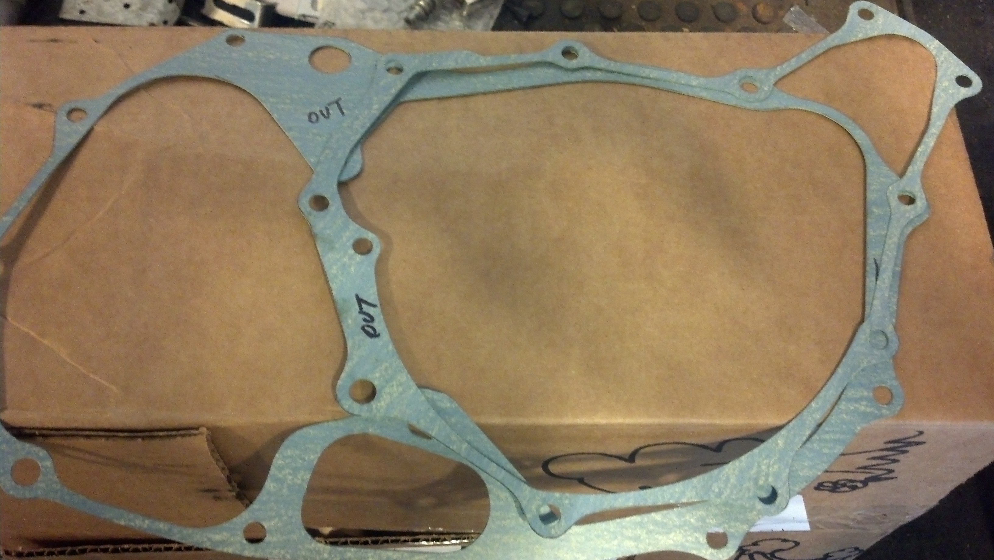
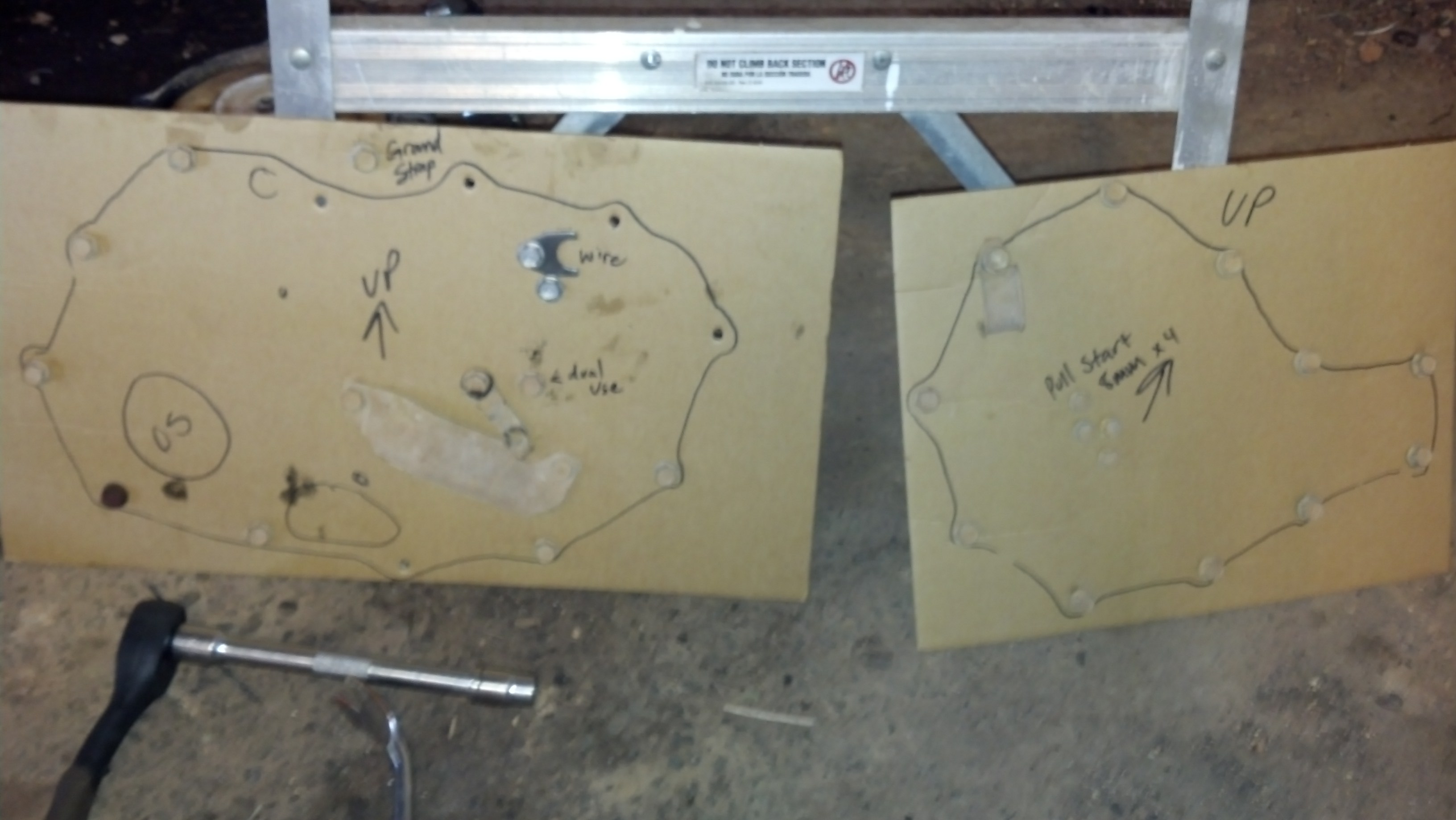
Before we turn any more wrenches, you'll notice your two gaskets have nice pieces of cardboard protecting
them. Lets use those as drawing boards and trace them. Then punch the bolt holes with a screwdriver and
you have a handy place to store your bolts since there are several different sizes that will come out of this cover.
Now we are at the business end....let's start by pulling the 4 bolts that hold the kickstart cover on.
This cover has no gasket and no sealer. I recommend you use some rtv when it goes back together. You can
never be too careful.
---------
on the rear jackstands because I hooked a chain hoist to the rear and lifted it by the rafters.
Made it much easier to roll under with my stool.

This is pretty basic. Pull the driver's side tank plastic off, oil fill cover, and complete airbox
assembly. That's basically it, you can see the entire rear of the engine once that is removed.

Make sure you have all the right parts:

Before we turn any more wrenches, you'll notice your two gaskets have nice pieces of cardboard protecting
them. Lets use those as drawing boards and trace them. Then punch the bolt holes with a screwdriver and
you have a handy place to store your bolts since there are several different sizes that will come out of this cover.

Now we are at the business end....let's start by pulling the 4 bolts that hold the kickstart cover on.
This cover has no gasket and no sealer. I recommend you use some rtv when it goes back together. You can
never be too careful.

---------
Aug 25, 2014 | 10:50 PM
#3
Thread Starter
|
Pro Rider
Joined: Aug 2010
Posts: 230
Likes: 0
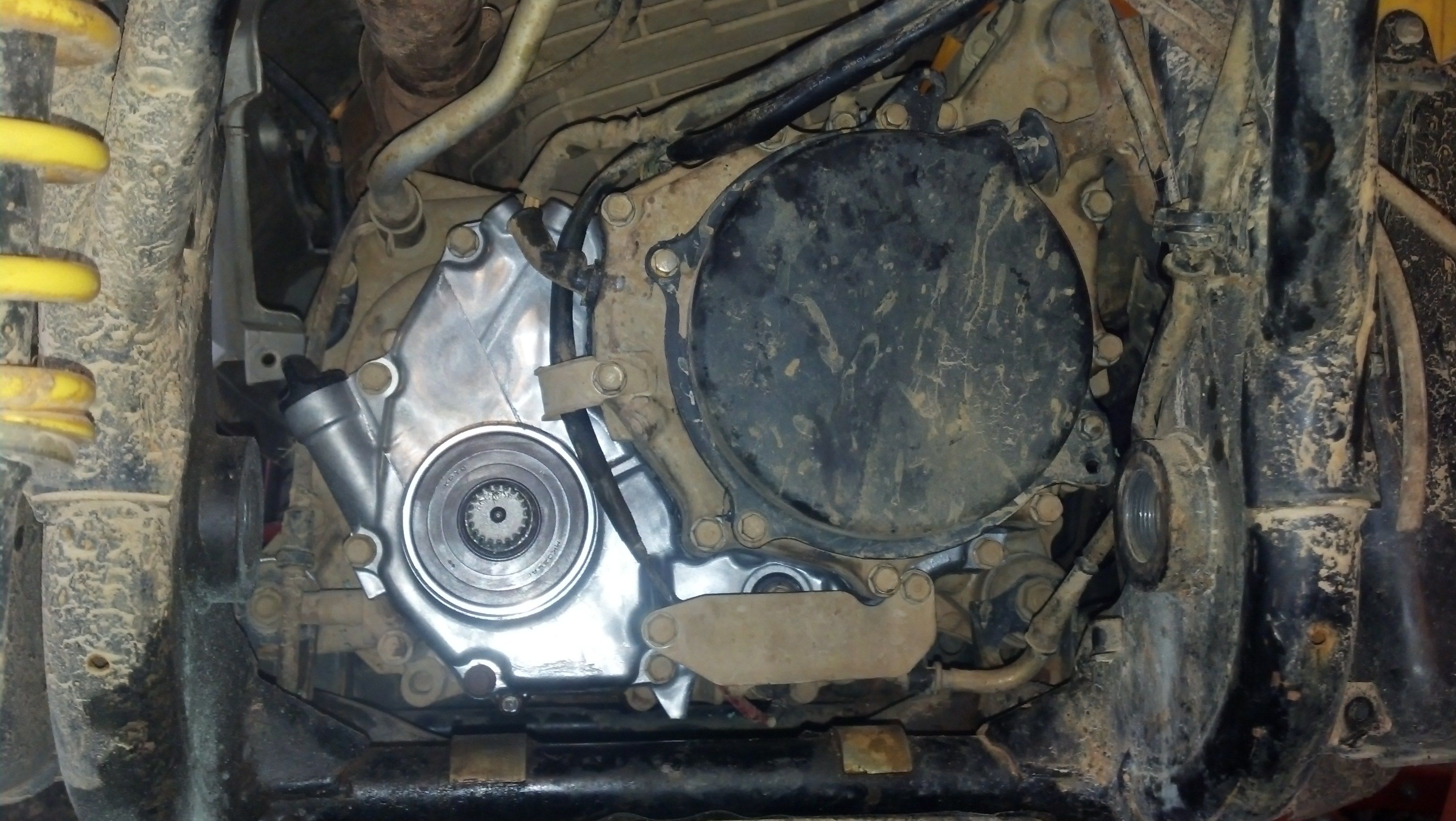
Here's what you'll find under that black cover. I believe this is a 17mm. An impact gun zipped it out.
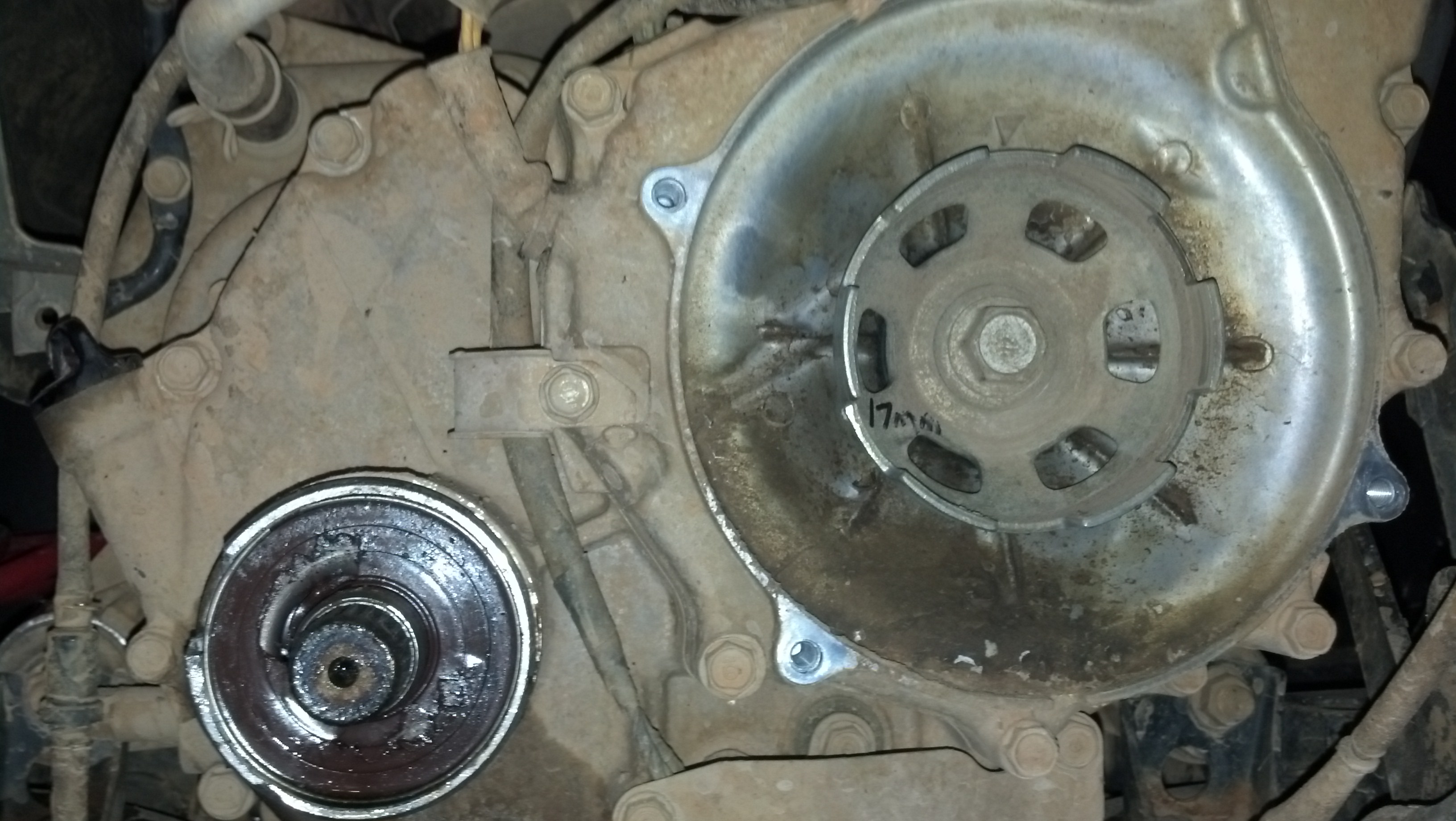
Notice the long bolt has an O'ring seal on it. Inspect it and replace it if necessary. Mine looked fine.
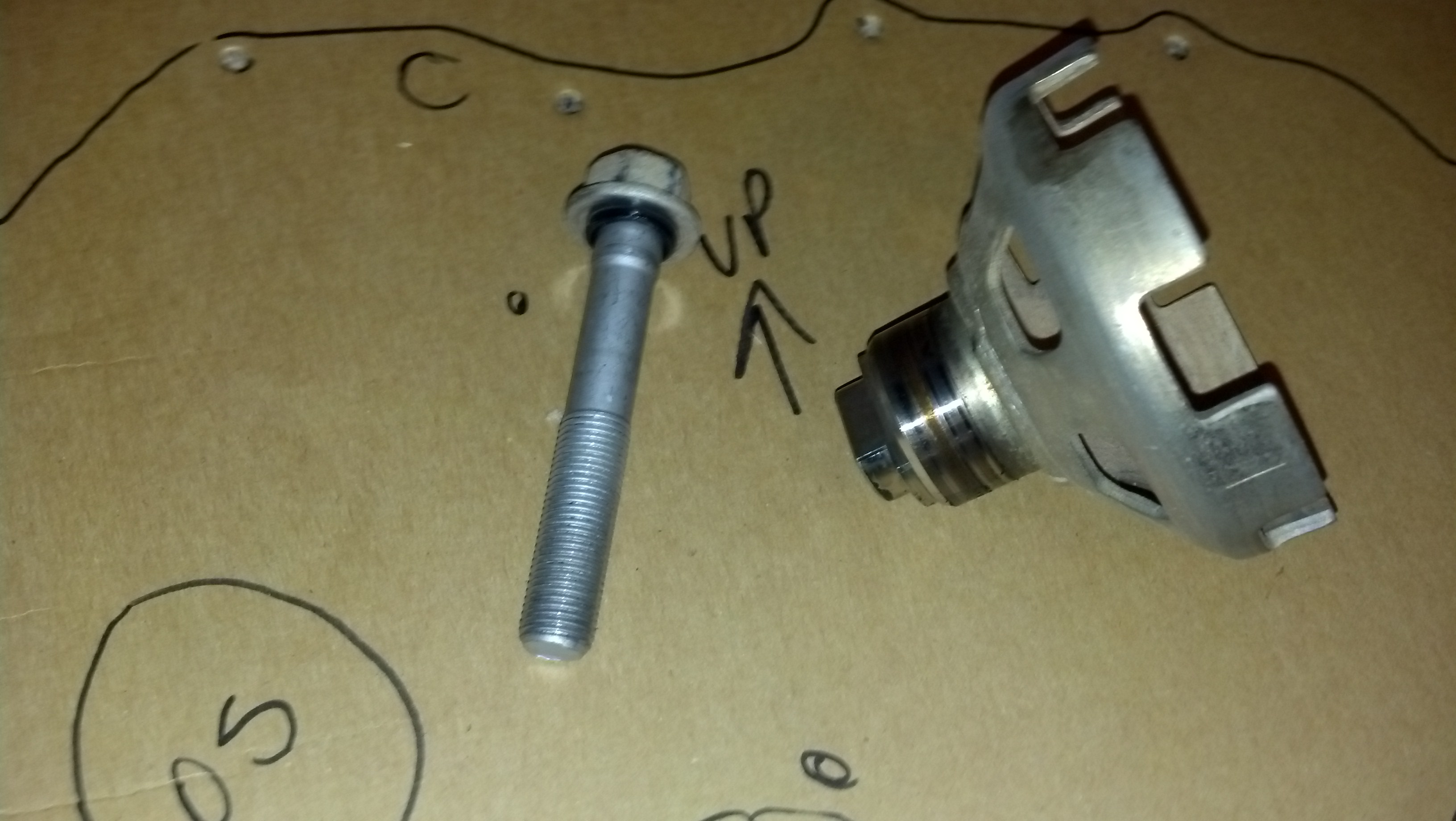
Next is the crap on the bottom of the cover. The two electrical connectors simply pull straight off, and the cable and brackets will need to be unbolted. The bolt holding the black bracket is a dual use bolt, meaning it holds the bracket but is a critical fastener for the cover as well. The one holding the silver cable bracket is not.
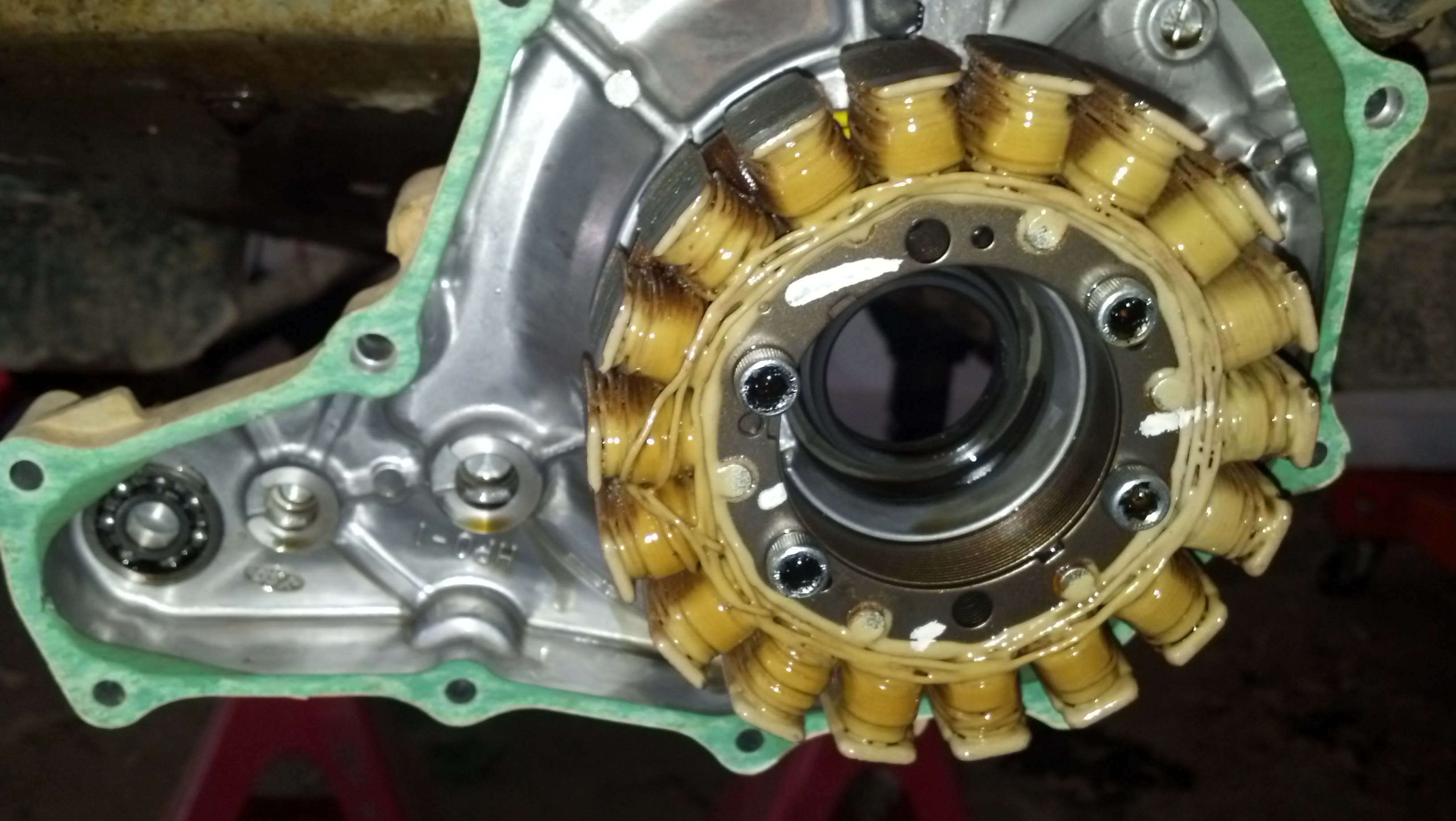
Here's what's under the kickstart cover. This is how your ATV makes its own electricity. Basically, an alternator.
The backside of the cover itself:
--------------------

Notice the long bolt has an O'ring seal on it. Inspect it and replace it if necessary. Mine looked fine.

Next is the crap on the bottom of the cover. The two electrical connectors simply pull straight off, and the cable and brackets will need to be unbolted. The bolt holding the black bracket is a dual use bolt, meaning it holds the bracket but is a critical fastener for the cover as well. The one holding the silver cable bracket is not.

Here's what's under the kickstart cover. This is how your ATV makes its own electricity. Basically, an alternator.

The backside of the cover itself:

--------------------
Aug 25, 2014 | 10:54 PM
#4
Thread Starter
|
Pro Rider
Joined: Aug 2010
Posts: 230
Likes: 0
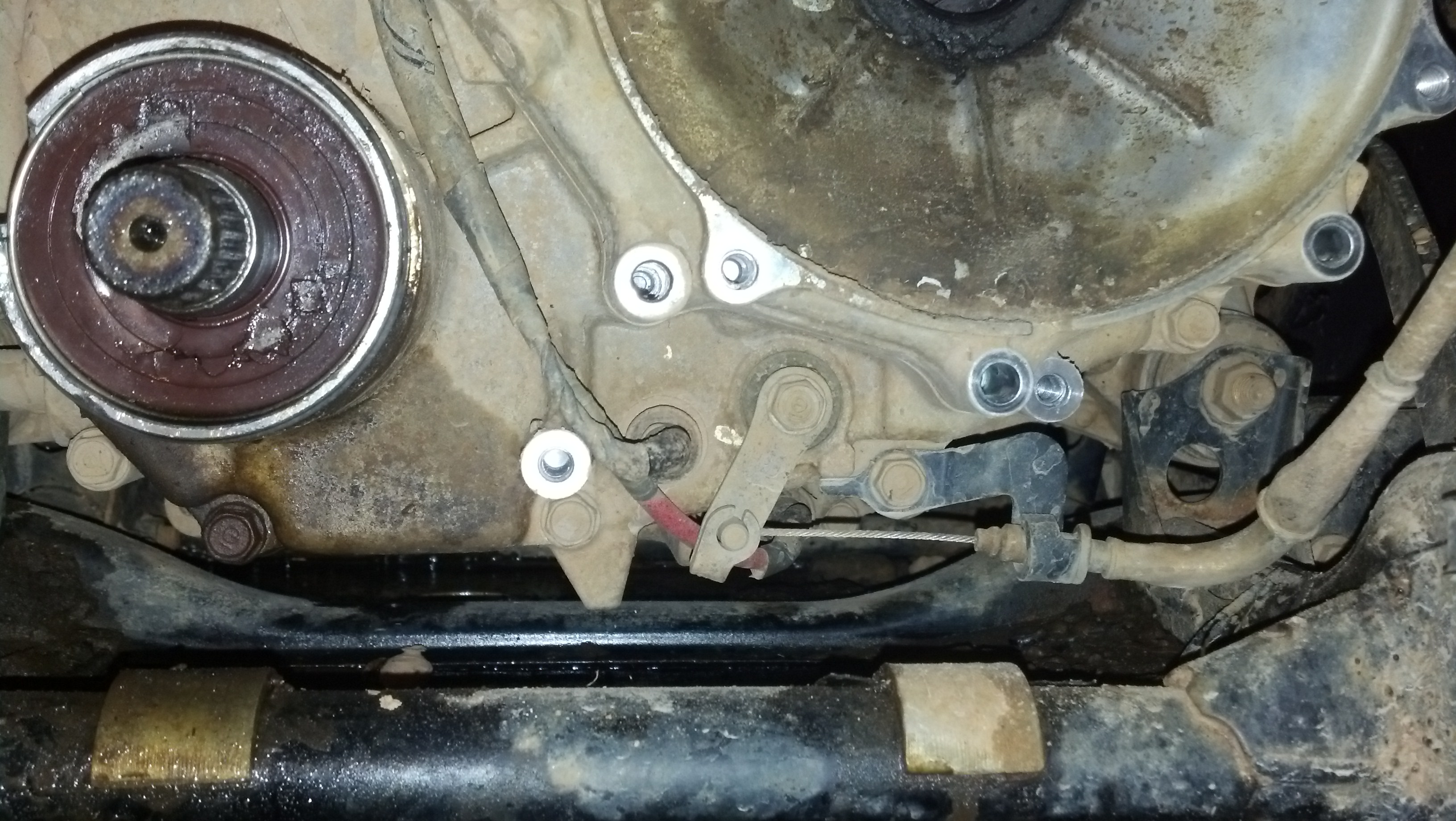
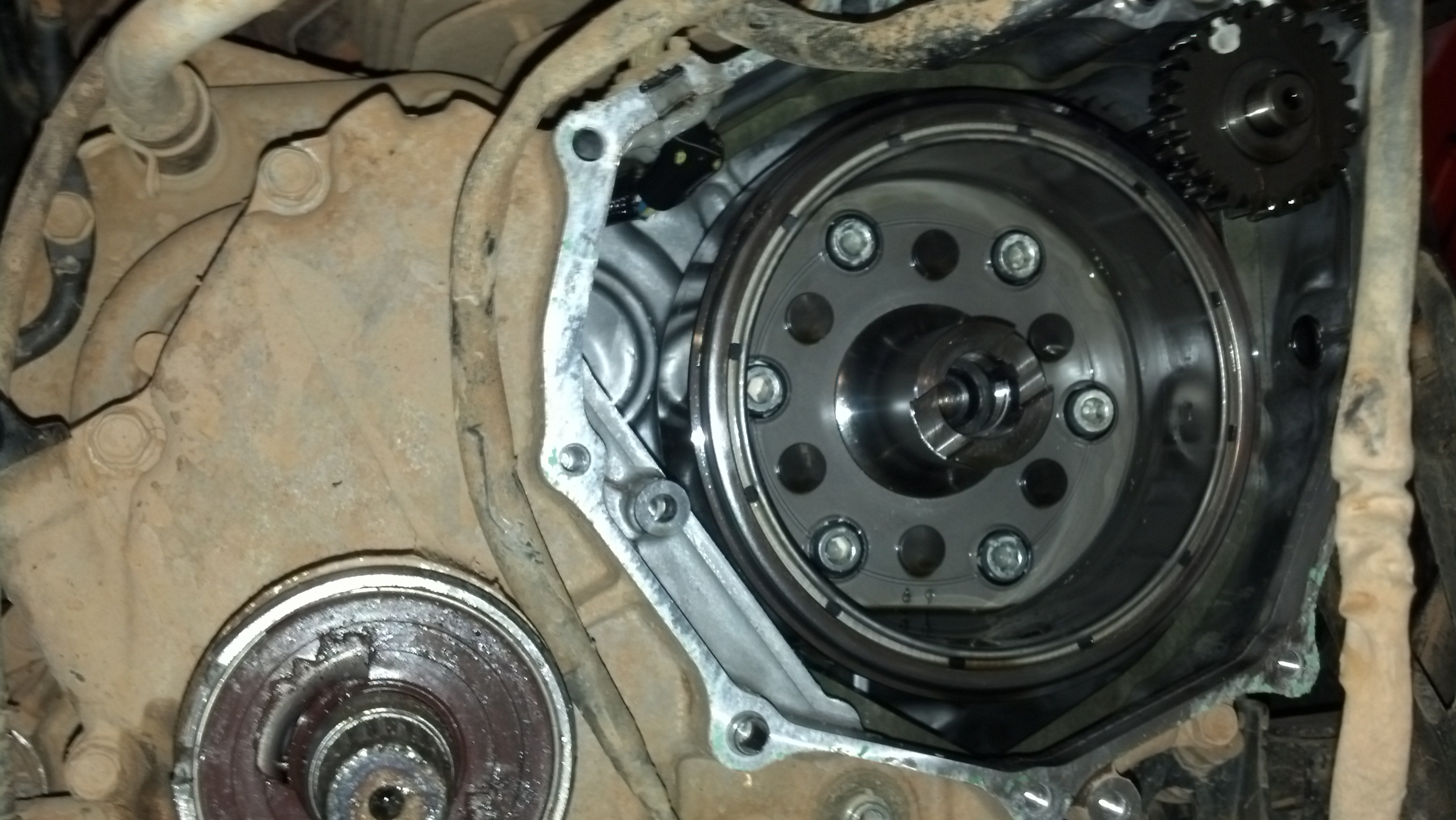
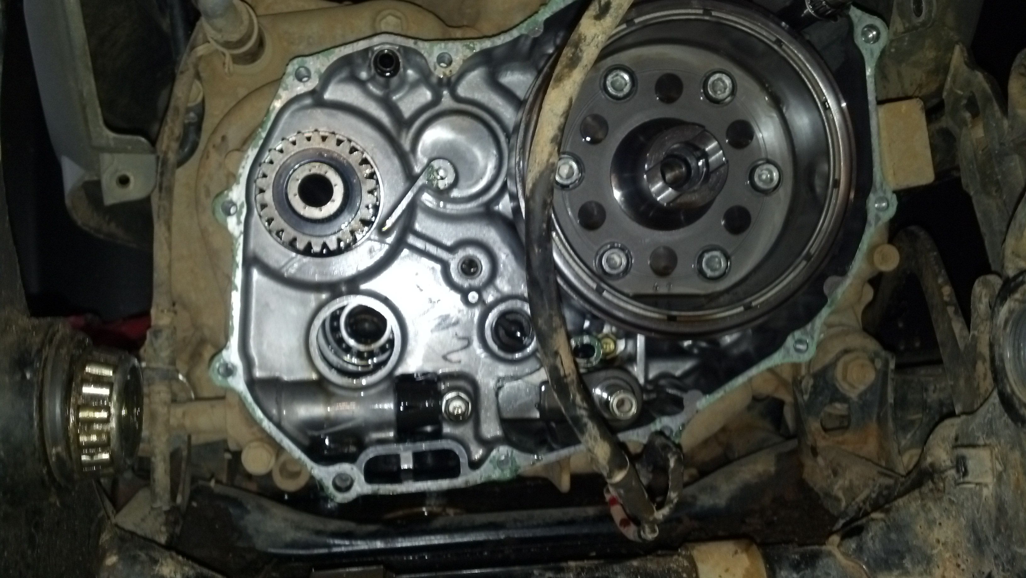
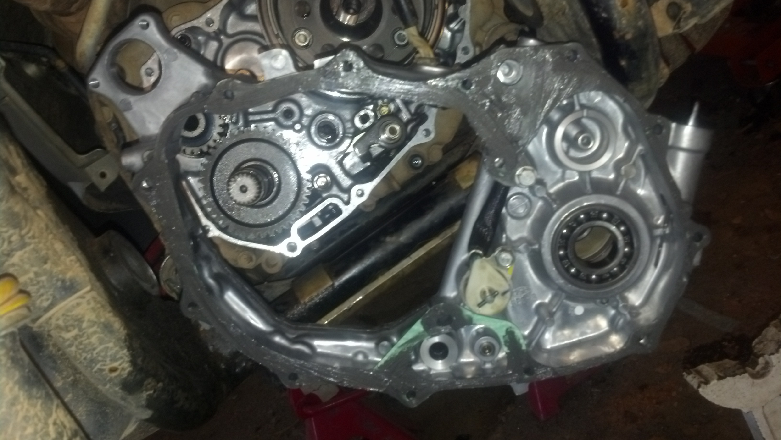
Undo the rest of the perimeter bolts and this is what she looks like opened up: Note, I've already pulled the
output shaft in this picture. I was inserted into the hole in the bottom left of the engine.
And here it is all bugared up:
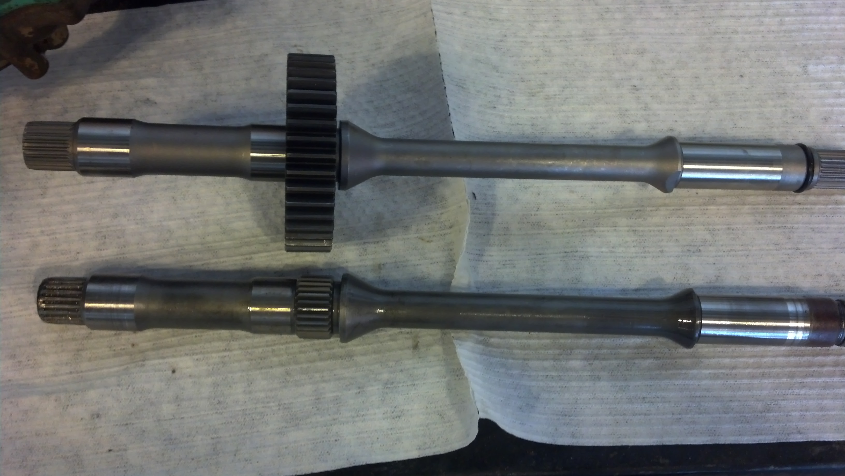
New next to old, the gear just slides off and transfers over.
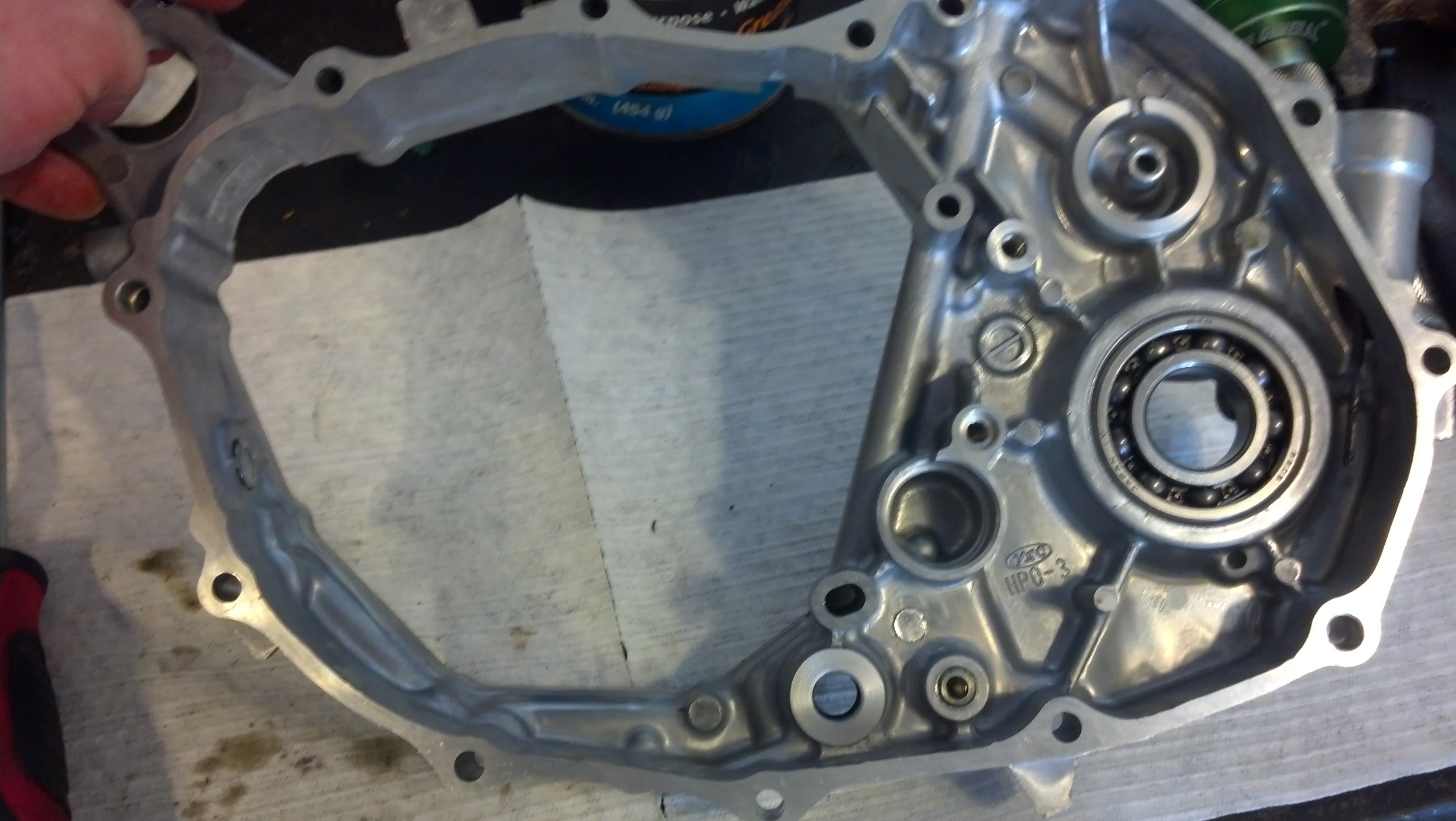
Here's our old cover, we need to move the electrical switch and wiring over to the new cover, as well as
the output shaft bearing. Mine just fell out for some reason, but required some hammer tapping to insert
it into the new cover which was odd.
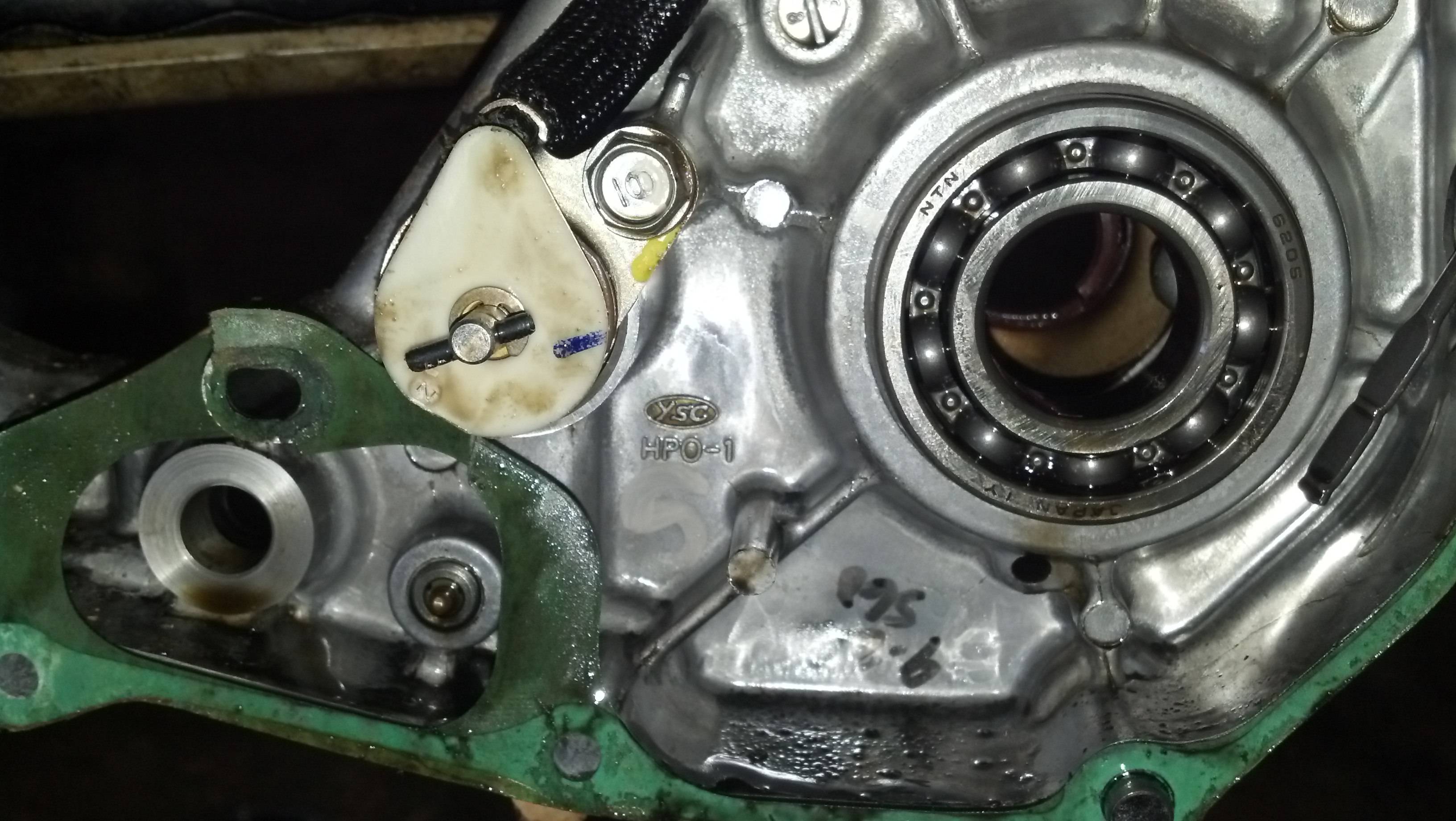
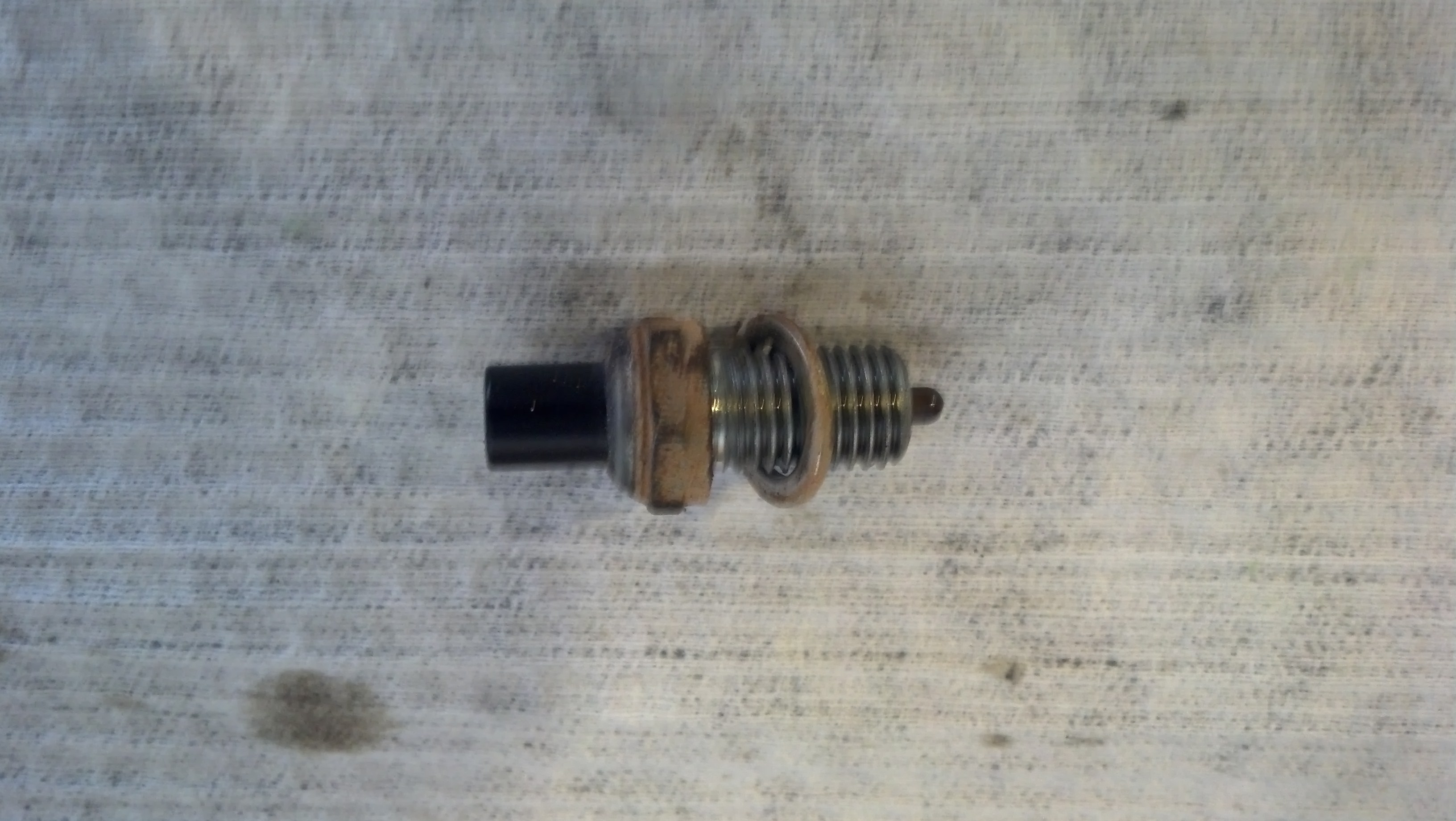
This sensor located bottom center must be transfered:
-------------------
output shaft in this picture. I was inserted into the hole in the bottom left of the engine.

And here it is all bugared up:

New next to old, the gear just slides off and transfers over.

Here's our old cover, we need to move the electrical switch and wiring over to the new cover, as well as
the output shaft bearing. Mine just fell out for some reason, but required some hammer tapping to insert
it into the new cover which was odd.

This sensor located bottom center must be transfered:

-------------------
Aug 25, 2014 | 10:55 PM
#5
Thread Starter
|
Pro Rider
Joined: Aug 2010
Posts: 230
Likes: 0
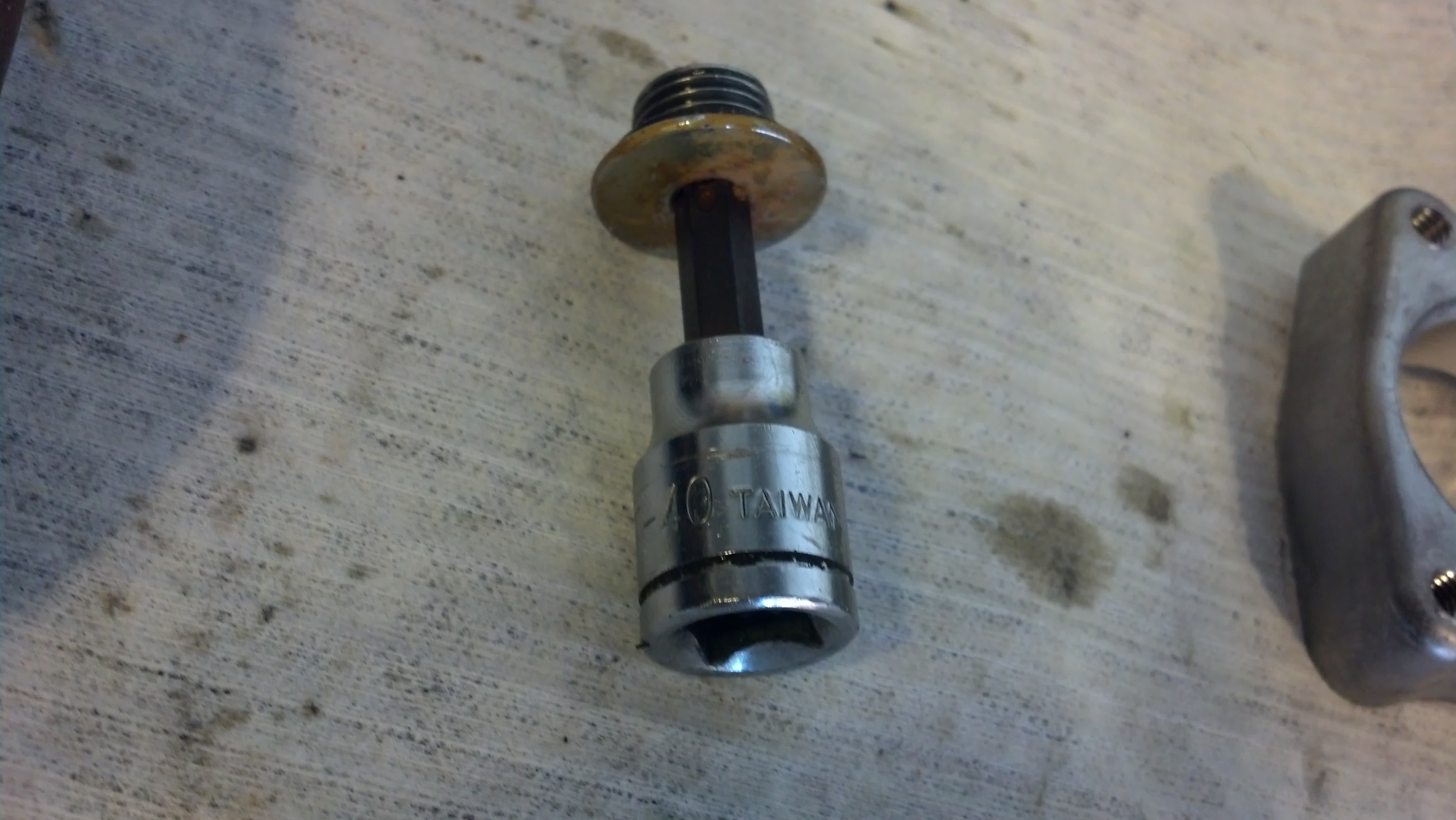
As well as this plug on the top corner (note the o'ring seal on this one too): Doesnt that say t-40?
New cover prepped and ready to go back on:
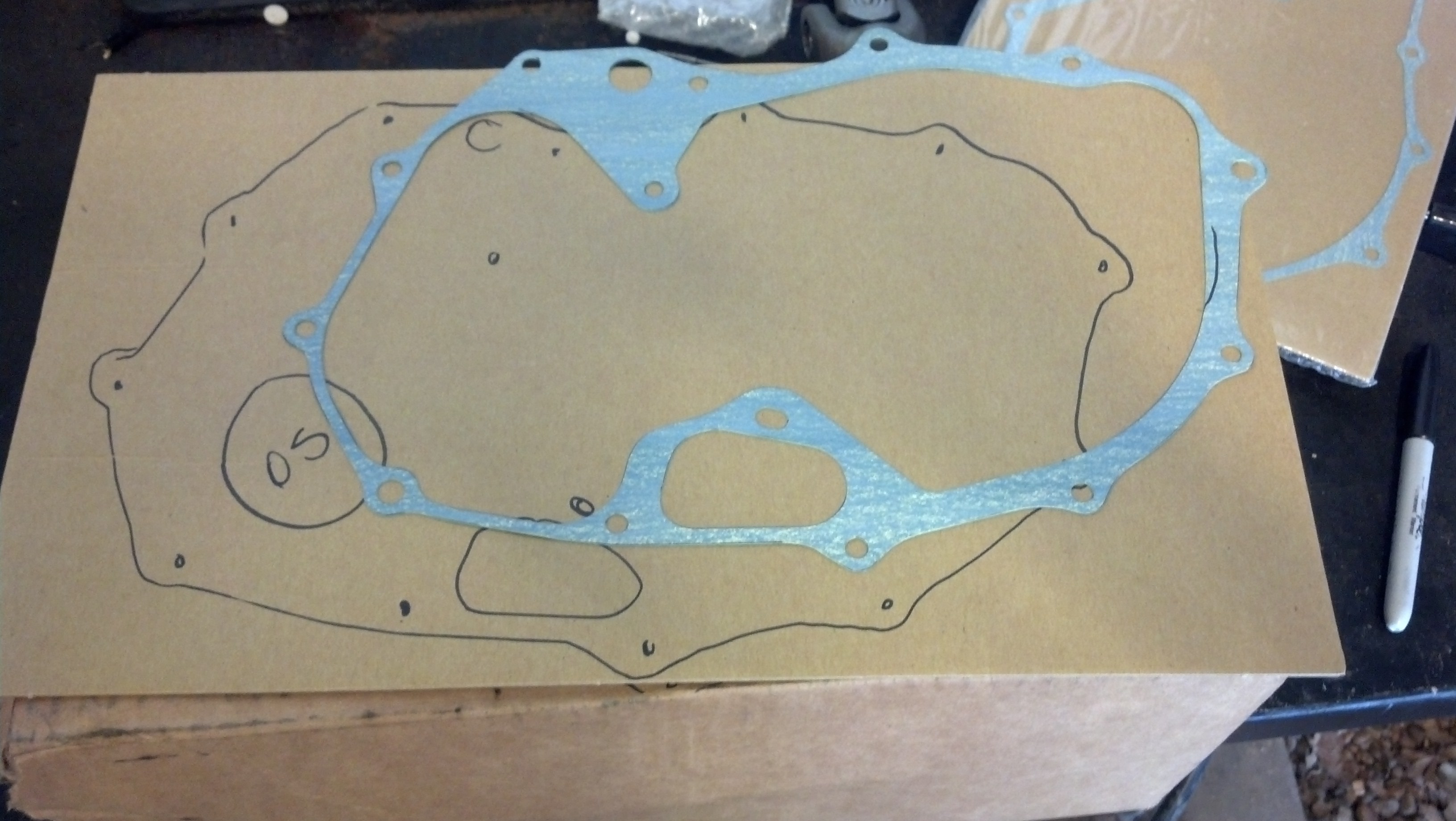
You'll note that on your cardboard some bolt holes are missing...that because some hold both covers and go through
both gaskets. I have lined the gaskets up in this picture so you can see where they overlap:
Here's my artwork:
So for the two main gaskets, i do a prep with a gasket prep disc on a pnuematic grinder, then a super
thin layer of Ultra Black RTV, then the gasket, then another layer of RTV. Works everytime. Ready for assembly.
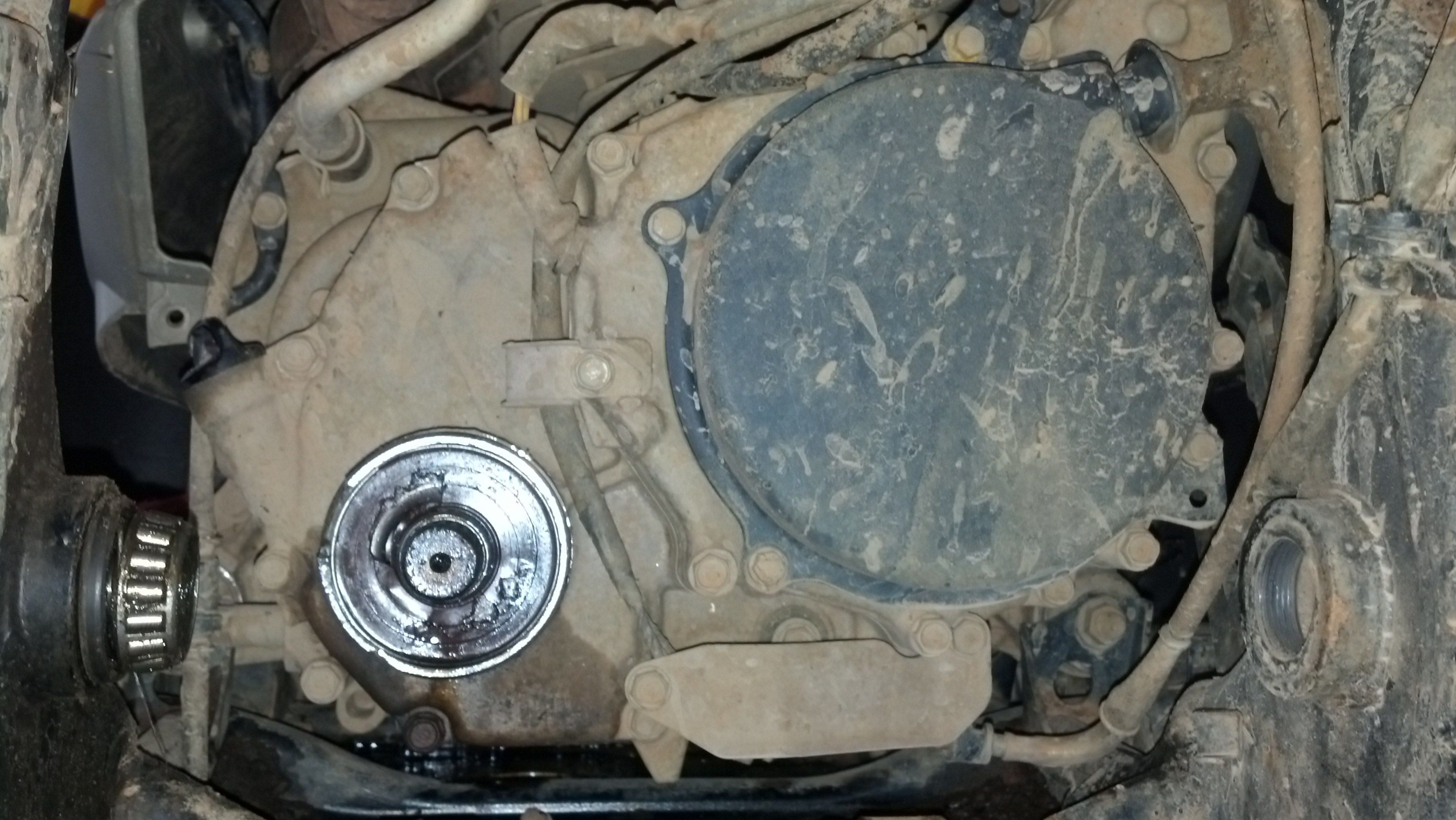
Reinstall everything and this is how she should look: Dont forget to seal your kickstart cover.
Thoughts, comments, suggestions? As an FYI, that was a Moose Racing U joint that broke (part# 1205-0201). Pure junk.

New cover prepped and ready to go back on:

You'll note that on your cardboard some bolt holes are missing...that because some hold both covers and go through
both gaskets. I have lined the gaskets up in this picture so you can see where they overlap:

Here's my artwork:

So for the two main gaskets, i do a prep with a gasket prep disc on a pnuematic grinder, then a super
thin layer of Ultra Black RTV, then the gasket, then another layer of RTV. Works everytime. Ready for assembly.

Reinstall everything and this is how she should look: Dont forget to seal your kickstart cover.

Thoughts, comments, suggestions? As an FYI, that was a Moose Racing U joint that broke (part# 1205-0201). Pure junk.

Trending Topics
Feb 5, 2023 | 11:25 PM
#9

Weekend Warrior
Joined: Feb 2023
Posts: 1
Likes: 0
As well as this plug on the top corner (note the o'ring seal on this one too): Doesnt that say t-40?
Attachment 13868
New cover prepped and ready to go back on:
Attachment 13869
You'll note that on your cardboard some bolt holes are missing...that because some hold both covers and go through
both gaskets. I have lined the gaskets up in this picture so you can see where they overlap:
Attachment 13870
Here's my artwork:
Attachment 13871
So for the two main gaskets, i do a prep with a gasket prep disc on a pnuematic grinder, then a super
thin layer of Ultra Black RTV, then the gasket, then another layer of RTV. Works everytime. Ready for assembly.
Attachment 13872
Reinstall everything and this is how she should look: Dont forget to seal your kickstart cover.
Attachment 13873
Thoughts, comments, suggestions? As an FYI, that was a Moose Racing U joint that broke (part# 1205-0201). Pure junk.
the only question I have is the out put shaft does he just slide in and out or if there a clip or anything for taking him out once you got the back piece off or?
Feb 6, 2023 | 03:20 AM
#10

Elite Pro Rider


Joined: Oct 2013
Posts: 7,483
Likes: 387
From: Lancaster England
They can stick on that O ring which is on the front end of the shaft, in my opinion, better to take the ring off as you slide it out. Remember to put the O ring back on before you slide the shaft into the front prop shaft coupling as you put it back.

Thread
Thread Starter
Forum
Replies
Last Post
ATVC Correspondent
Classifieds, Garage Sale & Swap Shop
0
Jul 22, 2015 05:00 AM
joeyupton
Polaris Ask an Expert! In fond memory of Old Polaris Tech.
1
Jul 14, 2015 11:51 AM
Currently Active Users Viewing This Thread: 1 (0 members and 1 guests)