
no spark on FSN 110cc
 Jul 18, 2011 | 11:52 PM
#11

Weekend Warrior
Joined: Jul 2011
Posts: 9
Likes: 0
i change all the parts on the typhoon but still nothing the only thing i messing right now with.... they sent me the wrong left switch assembly on the wired harnees i got 7 pin on the assembly 9 pin so i swap the wires so i thing im not getting ground to cdi or etc any body can help me with this please.....
Jul 19, 2011 | 10:15 PM
#12
Weekend Warrior
Joined: Jul 2011
Posts: 9
Likes: 0
i had a typhoon 110 how u math the wires from harness to stator my stator has 5 pins yellow, green ,black/red,blue/white, and white do i match by color or another way can somebody help me please im breaking my head .........
Jul 19, 2011 | 10:16 PM
#13
Weekend Warrior
Joined: Jul 2011
Posts: 9
Likes: 0
i had a typhoon 110 how u math the wires from harness to stator my stator has 5 pins yellow, green ,black/red,blue/white, and white do i match by color or another way can somebody help me please im breaking my head .........
Jul 19, 2011 | 11:22 PM
#14

Electrical Expert
Likes High Voltage In The Tub!
Likes High Voltage In The Tub!
Joined: Dec 2008
Posts: 3,260
Likes: 14
From: Tracy, California, USA
i change all the parts on the typhoon but still nothing the only thing i messing right now with.... they sent me the wrong left switch assembly on the wired harnees i got 7 pin on the assembly 9 pin so i swap the wires so i thing im not getting ground to cdi or etc any body can help me with this please.....

You need a meter. Meters are cheap, and (with a little help) can be a very powerful tool.
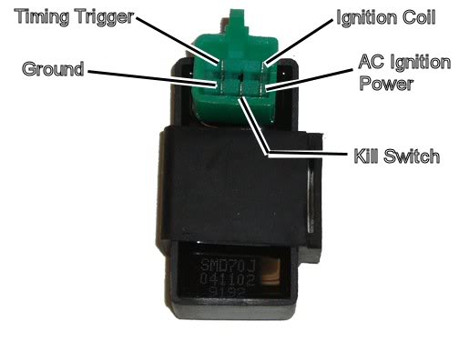
I don't know anything about typhoon 110cc quads. Is this a four stroke? Does the CDI look like this?
Rather than try to wire in a known wrong switch on top of your existing problems, I would put the old switch back. Maybe I would try to put back all the old components too so that we're working with just one problem, not two (or even several). The get out your meter
 .
Jul 19, 2011 | 11:25 PM
.
Jul 19, 2011 | 11:25 PM
#15
Electrical Expert
Likes High Voltage In The Tub!
Likes High Voltage In The Tub!
Joined: Dec 2008
Posts: 3,260
Likes: 14
From: Tracy, California, USA
 .
Jul 20, 2011 | 11:25 PM
.
Jul 20, 2011 | 11:25 PM
#17
Electrical Expert
Likes High Voltage In The Tub!
Likes High Voltage In The Tub!
Joined: Dec 2008
Posts: 3,260
Likes: 14
From: Tracy, California, USA
The wires that have anything to do with your ignition system are:
Blk/Red: AC Ignition Power
Blu/Wht: Ignition Trigger
Green: Ground
The yellow and white white are for the battery charging circuitry, which has nothing to do with ignition.
Here is the generic "no spark" troubleshooting procedure for a five pin CDI:
The first thing to do is eliminate all kill switches abd kill switch wiring:
Method 1) Unplug the CDI and remove the kill switch pin in the CDI connector on the wiring harness. The pin is held in with a spring tab on the pin itself. You'll have to probe into the connector and push this tab in order to extract the pin. Plug the CDI back in (kill switch wire dangling) and see if you have spark.
Method 2) Unplug the CDI. Turn on the ignition switch and set all kill switches to the run position. Use a meter to measure resistance in of the kill switch pin in the wiring harness connector to engine/frame ground. If the reistance is infinite on the 100K ohm scale then your kill switches/kill switch wiring are OK. If you measure zero ohms then you have a kill switch/wiring issue.
The other inputs your CDI needs to make spark are AC Ignition Power, and the Trigger signal. Do the following:
1) Unplug the CDI. In the wiring connector measure the resistance of the AC Ignition Power pin to the Ground pin. You should see 400 ohms or so. What do you measure?
2) Measure the resistance of the Timing/trigger pin to the ground pin. You should measure 150 ohms or so. What do you measure?
3) Leave the CDI unplugged. Set your meter to measure AC volts on the 100 volt scale. Measure the voltage on the AC Ignition Power pin to the ground pin while cranking the engine. You should see 40 to 80 volts AC while the engine is cranking. What do you measure?
4) Set your meter to measure AC volts on the lowest scale you have. Ideally this would be 2 volts but many meters don't go down this low. In that case use the lowest scale you have. Measure the voltage on the Timing Trigger pin to the Ground pin while cranking the engine. You should 0.2 t0 0.4 volts AC. What do you measure?
Now for measuring the output side of the CDI:
A) Leave the CDI unplugged. In the CDI wiring connector measure the resistance of the Ignition Coil pin to the ground pin. You should measure less than 1 ohm (but not zero ohms). What do you measure?
B) Plug the CDI back in. Set your meter to measure AC volts on the 20 volt scale. Set all kill switches to the run position. Crank the engine while measuring the voltage on the Igntition Coil pin to ground. Poke through the insulation of the wire if you can't probe the connector.
Caution: There should be moderately high voltage spikes on this wire. Make sure your fingers are not part of the circuitry. Don't touch the probe lead tips while doing this test.
What you should see is a lot of random numbers with lots of zero values as well. This is because the meter may catch all or part of the spark event voltage, with a lot of nothing in between. Describe what you see.
Note: Using a meter to measure this point produces highly variable results depending on the meter. What you really need is an oscilloscope, but most always a meter is all that is available. We have to do the best we can with what's available. Describe the meter results as accurately as you can - there is information there to chew on....