
4 wires from stator ?
 Jul 15, 2010 | 01:29 PM
#1

Thread Starter
|
Weekend Warrior
Joined: Jul 2010
Posts: 13
Likes: 0
changed 250 engine in hi-bird QH250 STW old stator had 4 wires 3 yellow and 1 black & red. New engine only has 3 yellow ones.How do I power the black & red one ? Tried wire from battery but blew up the CDI
Jul 15, 2010 | 11:26 PM
#2

Electrical Expert
Likes High Voltage In The Tub!
Likes High Voltage In The Tub!
Joined: Dec 2008
Posts: 3,260
Likes: 14
From: Tracy, California, USA
There actually should be more wires than that:
1) The three yellow wires are the 3 phase output of the battery carge windings.
2) The red/blk wire on your old stator is a moderately high voltage winding that powers your old CDI.
3) There should also be a Timing Trigger wire (usually blue/white, but not always) that tells the CDI when to fire.
4) There is also usually a redundant ground wire (usually green or black) that ties the ground return of the trigger coil (and the high voltage ignition power coil) to frame ground. It is redundant because the ground return wire is already grounded to the stator frame internally.
You can get away with the redundant ground wire missing, but you can't get away with the timing trigger wire missing. I bet if you look for it you will find it. It comes from a small pickup coil mounted outside the flywheel. It goes to the CDI, but sometime it goes via a kill switch. Most of the time it just goes directly.
The missing black/red wire on stators is becoming a very common problem. Before a couple years ago all CDI's were powered with AC voltage from a separate winding on the stator at 50-300 volts (depending on engine speed). Now days more and more CDI's are powered from 12 volts directly. These CDI's still run on high voltage internally - the new CDI's have an internal switching power supply that converts the 12 volts to the moderately high voltage necessary for the CDI to work.
The bad news is that the two CDI's (high voltage AC powered, and 12 DC powered) look identical. You can't tell the difference just by looking, though sometimes the DC powered CDI's are a little bigger because they have that extra conversion power supply inside. They are not compatible. You have to use the right one.
I bet this is a picture of your CDI:
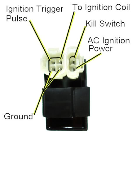
When you try to power an AC powered CDI off 12 volts DC from the battery you usually get smoke, and often a loud bang following by a new hole in the CDI that wasn't there before. I suspect that is what happened to your old (and now toasted) CDI.
So here is what you need to do. Buy a new CDI, but make sure it is a *DC* powered version. Ask, and if the vendor doesn't know what you are talking about then shop elsewhere. Then run DC power to it just like you did with the old one only make sure it is *switched* 12 volt power from the ignition switch.
I'm not positive if the kill switch connection works to kill spark on all DC powered CDI's. Try it and see. If is doesn't there are simple rewire steps to take to remedy that. In any case if you wire the DC power to the CDI through the ignition switch, then you can always use the ignition switch to turn off the power to the CDI (killing spark).
1) The three yellow wires are the 3 phase output of the battery carge windings.
2) The red/blk wire on your old stator is a moderately high voltage winding that powers your old CDI.
3) There should also be a Timing Trigger wire (usually blue/white, but not always) that tells the CDI when to fire.
4) There is also usually a redundant ground wire (usually green or black) that ties the ground return of the trigger coil (and the high voltage ignition power coil) to frame ground. It is redundant because the ground return wire is already grounded to the stator frame internally.
You can get away with the redundant ground wire missing, but you can't get away with the timing trigger wire missing. I bet if you look for it you will find it. It comes from a small pickup coil mounted outside the flywheel. It goes to the CDI, but sometime it goes via a kill switch. Most of the time it just goes directly.
The missing black/red wire on stators is becoming a very common problem. Before a couple years ago all CDI's were powered with AC voltage from a separate winding on the stator at 50-300 volts (depending on engine speed). Now days more and more CDI's are powered from 12 volts directly. These CDI's still run on high voltage internally - the new CDI's have an internal switching power supply that converts the 12 volts to the moderately high voltage necessary for the CDI to work.
The bad news is that the two CDI's (high voltage AC powered, and 12 DC powered) look identical. You can't tell the difference just by looking, though sometimes the DC powered CDI's are a little bigger because they have that extra conversion power supply inside. They are not compatible. You have to use the right one.
I bet this is a picture of your CDI:
When you try to power an AC powered CDI off 12 volts DC from the battery you usually get smoke, and often a loud bang following by a new hole in the CDI that wasn't there before. I suspect that is what happened to your old (and now toasted) CDI.
So here is what you need to do. Buy a new CDI, but make sure it is a *DC* powered version. Ask, and if the vendor doesn't know what you are talking about then shop elsewhere. Then run DC power to it just like you did with the old one only make sure it is *switched* 12 volt power from the ignition switch.
I'm not positive if the kill switch connection works to kill spark on all DC powered CDI's. Try it and see. If is doesn't there are simple rewire steps to take to remedy that. In any case if you wire the DC power to the CDI through the ignition switch, then you can always use the ignition switch to turn off the power to the CDI (killing spark).
Jul 16, 2010 | 12:52 PM
#3
Thread Starter
|
Weekend Warrior
Joined: Jul 2010
Posts: 13
Likes: 0
Thank you, yes that is what happend when we did the wire off the battery.The other 2 wires off the trigger were hooked up but had that black wire left over from the cdi.The parts store gave me a cdi for a honda trx250r that is bigger than the old but the plugs are the same.They did not know if it was ac or dc.I will try it out ,I think it is dc because it is wider than the old one like you said it mite be.
Jul 16, 2010 | 11:41 PM
#4
Electrical Expert
Likes High Voltage In The Tub!
Likes High Voltage In The Tub!
Joined: Dec 2008
Posts: 3,260
Likes: 14
From: Tracy, California, USA
Give the honda CDI a try but keep in mind that the "DC version CDI's are often bigger" is statistically accurate overall but not an absolute guarantee for an individual CDI.
I've seen eBay listings for DC CDI's with the same connector arrangement shown previously. I've never bought one though so I can't vouch for their veracity. On the www.buggynews.com site there are regular posters that are also parts vendors that sell DC CDI's. They are *very* aware of the difference between DC and AC CDI's since Hammerhead buggies have both kinds of CDI's and it is a constant cause of confusion.
I've seen eBay listings for DC CDI's with the same connector arrangement shown previously. I've never bought one though so I can't vouch for their veracity. On the www.buggynews.com site there are regular posters that are also parts vendors that sell DC CDI's. They are *very* aware of the difference between DC and AC CDI's since Hammerhead buggies have both kinds of CDI's and it is a constant cause of confusion.
Jul 19, 2010 | 05:47 PM
#5
Thread Starter
|
Weekend Warrior
Joined: Jul 2010
Posts: 13
Likes: 0
the plugs on that CDI that I got did not fit my plugs. The 2 wire plug was to small on the CDI an tht 4 wire had round corners on it . Got one from buyatvsonline.com, it has the right plugs ,put it in an nosmoke or bang.BUT no spark,no power in wire from CDI to coil.Tried to test trigger power with it cranking no voltage in blue& white wire.
Jul 19, 2010 | 11:27 PM
#6
Electrical Expert
Likes High Voltage In The Tub!
Likes High Voltage In The Tub!
Joined: Dec 2008
Posts: 3,260
Likes: 14
From: Tracy, California, USA
the plugs on that CDI that I got did not fit my plugs. The 2 wire plug was to small on the CDI an tht 4 wire had round corners on it . Got one from buyatvsonline.com, it has the right plugs ,put it in an nosmoke or bang.BUT no spark,no power in wire from CDI to coil.Tried to test trigger power with it cranking no voltage in blue& white wire.
Also measure the resistance of this harness wire to ground (CDI disconnected). It should measure about 150 ohms.
If you don't have a trigger signal you won't get spark.
Jul 19, 2010 | 11:35 PM
#7
Thread Starter
|
Weekend Warrior
Joined: Jul 2010
Posts: 13
Likes: 0
blue&white wire =.2 volts, Yellow wires (3) 7.9 volts between each from stator.
How do I check the ohms ?
How do I check the ohms ?
Trending Topics
Jul 19, 2010 | 11:58 PM
#8
Electrical Expert
Likes High Voltage In The Tub!
Likes High Voltage In The Tub!
Joined: Dec 2008
Posts: 3,260
Likes: 14
From: Tracy, California, USA
Switch the meter over to the ohms scale. Sometimes the meter uses the capital greek letter omega to label the "ohms" scales. It looks like a horseshoe symbol with the ends pointing down (you could google omega to see).
When you short the meter leads together on all ohms scales the resistance will go to zero ohms. When the leads are separated the resistance will go to infinity. You want to use somewhere near the 200 ohm scale.
You did verify that you have 12 volts on the CDI power pin right?
When you short the meter leads together on all ohms scales the resistance will go to zero ohms. When the leads are separated the resistance will go to infinity. You want to use somewhere near the 200 ohm scale.
You did verify that you have 12 volts on the CDI power pin right?
Jul 20, 2010 | 10:52 PM
#10
Electrical Expert
Likes High Voltage In The Tub!
Likes High Voltage In The Tub!
Joined: Dec 2008
Posts: 3,260
Likes: 14
From: Tracy, California, USA
Since your ignition system was working before the engine swap (I assume, anyway), then you're left with a new timing trigger signal (from the stator), and the new supposedly DC powered CDI. Everything else is the same unless something bad happened when the old CDI got smoked.
1) Do measure the stator trigger wire resistance to ground.
2) Make sure you have a ground to the CDI (use the meter to measure zero ohms on the lowest resistance scale).
3) Make sure the kill switch connection measures infinite ohms to ground on the highest resistance scale when the ignition switch is on and all kill switches set to the "run" position. Conversely, verify that the CDI kill switch wire is shorted to ground when the ignition switch is off or any of the kill switches are in the "stop" position.
4) Make sure the output wire of the CDI (to the coil) measures something like 0.3 ohms to ground (not zero ohms, and not infinite ohms).
If all of the above measure fine then all indicators point to the CDI. Don't measure them just once. Do it several times and make sure you get the same answer every time. Consistant results generates confidence, and keeps you from going down blind alleys based on faulty data (and generating loads of frustration instead of confidence).