
stator 110 kazuma falcon (help)
 Aug 15, 2010 | 06:48 PM
#1

Thread Starter
|
Weekend Warrior
Joined: Aug 2010
Posts: 11
Likes: 0
we got a brand new engine for a 110 falcon. the plug for the stator is differnt from the old one. the old one had 5 wires yellow,white,green,blue/white and a black/red. the new one has 4 wires 2 yellows,green and blue/white. I cut them and put yellow to yellow, white to yellow, green to green and blue/white to blue/white. the black/red go to a cda box but the new engine doesnt have that wire. i dont know if i even have the wire right. i have no spark. please HELP.
Aug 16, 2010 | 12:31 AM
#2

Electrical Expert
Likes High Voltage In The Tub!
Likes High Voltage In The Tub!
Joined: Dec 2008
Posts: 3,260
Likes: 14
From: Tracy, California, USA
This is starting to become a real common problem. Older engines all used the high voltage AC power winding inside the stator to power the ignition system. Newer engines have eliminated this winding and require that you use a DC powered CDI. These newer CDIs are powered directly off of the switched 12 volts from the ignition switch. Thus you will need a DC powered CDI and you will have to rewire.
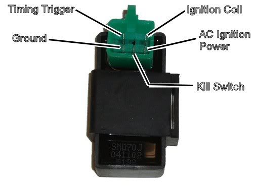
This is a 4 pin DC powered CDI:

This is a typical 5 pin AC powered CDI:
I'm also a little worried about your splicing the 2 yellow wires to the yellow and white wires. This may be trouble too, but that has nothing to do with spark. These wires are used to keep the battery charged through the voltage regulator. I suggest we ignore this for now and get the quad making spark and running by changing ans rewiring the CDI. Then we need to check the battery charging system and fix it if necessary.
This is a 4 pin DC powered CDI:
This is a typical 5 pin AC powered CDI:
I'm also a little worried about your splicing the 2 yellow wires to the yellow and white wires. This may be trouble too, but that has nothing to do with spark. These wires are used to keep the battery charged through the voltage regulator. I suggest we ignore this for now and get the quad making spark and running by changing ans rewiring the CDI. Then we need to check the battery charging system and fix it if necessary.
Aug 16, 2010 | 05:51 PM
#3
Thread Starter
|
Weekend Warrior
Joined: Aug 2010
Posts: 11
Likes: 0
I took the old stator out of the old engine and put it in the new engine. still no spark but the flyweel looks a little different. I dont no if i should try to chang the flyweel. it looks like it is prest on. or will that not make a differents? I talked to the people that i got the new engine. and that what thay told me to do. but dident work. Do you think i should still try a DC CDI box?
Aug 16, 2010 | 11:50 PM
#4
Electrical Expert
Likes High Voltage In The Tub!
Likes High Voltage In The Tub!
Joined: Dec 2008
Posts: 3,260
Likes: 14
From: Tracy, California, USA
What is different about the flywheel? Is it bigger? Is the number if magnets the same? What about the gap between the pickup coil and the raised bump on the flywheel? Is that gap the same?
On your AC ignition power pin in the wiring harness at the CDI connector (CDI disconnected, and old stator/new flywheel), what AC voltage do you measure while cranking the engine (all kill switches set to the run position)?
Set the voltmeter to the lowest AC scale you have. What AC voltage do you measure at the Timing trigger pin?
Have you tried disconnecting the kill wire at the CDI and see if you get spark?
Aug 17, 2010 | 10:02 AM
#5
Thread Starter
|
Weekend Warrior
Joined: Aug 2010
Posts: 11
Likes: 0
The raised bump on th flywheel is different. the gap looks the some. I tried disconnecting the kill switch and still no spark. if i am useing the voltmeter right i have 2 volts when cranking it over.
Aug 17, 2010 | 11:52 PM
#7
Electrical Expert
Likes High Voltage In The Tub!
Likes High Voltage In The Tub!
Joined: Dec 2008
Posts: 3,260
Likes: 14
From: Tracy, California, USA
2 volts (or 1 volt) does not fit either the AC ignition power or the timing trigger voltages at cranking speeds. You were supposed to report two voltages. I'm at a loss now because I don't know what you are doing.
Measure the timing trigger pin voltage at the CDI *and* the AC ignition power pin while cranking. The first will be low, but shouldn't be zero. The second will be much higher. What do you measure for both? Remember this is AC volts - not DC volts- so set your meter accordingly. Red lead on the pin being tested, and the black lead to engine (frame) ground.
Measure the timing trigger pin voltage at the CDI *and* the AC ignition power pin while cranking. The first will be low, but shouldn't be zero. The second will be much higher. What do you measure for both? Remember this is AC volts - not DC volts- so set your meter accordingly. Red lead on the pin being tested, and the black lead to engine (frame) ground.
Trending Topics
Aug 19, 2010 | 12:16 AM
#10
Electrical Expert
Likes High Voltage In The Tub!
Likes High Voltage In The Tub!
Joined: Dec 2008
Posts: 3,260
Likes: 14
From: Tracy, California, USA
Statements to the effect like "it measured good" are big red flags to me. How do you know it is good? I need less vague answers such as "I measured 38 volts AC, but it was bouncing around about 5 volts", or "I measured 65 volts AC steady as a rock while cranking".
Zero volts AC on the Timing trigger pin is wrong. This voltage is small though. What scale did you have the meter on? You want to be on the lowest scale possible - like 20 volts AC - so you are able to see very low voltages such as 0.3 volts.
Zero volts AC on the Timing trigger pin is wrong. This voltage is small though. What scale did you have the meter on? You want to be on the lowest scale possible - like 20 volts AC - so you are able to see very low voltages such as 0.3 volts.