
Army Vet. Needs Your Help
 Jan 10, 2011 | 05:01 PM
#11

Thread Starter
|
Weekend Warrior
Joined: Dec 2010
Posts: 16
Likes: 0
From: Central, MA
I forgot to address this issue in my last post...
How exactly did you determine that you were getting "current to the coil"? This isn't an easy measurement to make with just a meter, and subject to a lot of variation between different meters. I'm just curious about how you measured this, and what exactly were the results of these measurements? I'm looking for any information that gives clues to the problem...
How exactly did you determine that you were getting "current to the coil"? This isn't an easy measurement to make with just a meter, and subject to a lot of variation between different meters. I'm just curious about how you measured this, and what exactly were the results of these measurements? I'm looking for any information that gives clues to the problem...
 Jan 10, 2011 | 07:20 PM
#12
Thread Starter
|
Weekend Warrior
Joined: Dec 2010
Posts: 16
Likes: 0
From: Central, MA
I forgot to address this issue in my last post...
How exactly did you determine that you were getting "current to the coil"? This isn't an easy measurement to make with just a meter, and subject to a lot of variation between different meters. I'm just curious about how you measured this, and what exactly were the results of these measurements? I'm looking for any information that gives clues to the problem...
How exactly did you determine that you were getting "current to the coil"? This isn't an easy measurement to make with just a meter, and subject to a lot of variation between different meters. I'm just curious about how you measured this, and what exactly were the results of these measurements? I'm looking for any information that gives clues to the problem...
Jan 10, 2011 | 10:11 PM
#13

Electrical Expert
Likes High Voltage In The Tub!
Likes High Voltage In The Tub!
Joined: Dec 2008
Posts: 3,260
Likes: 14
From: Tracy, California, USA
The devil is in the details. When you do this again please report as much detailed description as you can...
Jan 10, 2011 | 10:16 PM
#14
Electrical Expert
Likes High Voltage In The Tub!
Likes High Voltage In The Tub!
Joined: Dec 2008
Posts: 3,260
Likes: 14
From: Tracy, California, USA
I have no idea what this is. I did a google search and found your picture below and several others that all look like CDI's. I'm continuing to look into this....
What color wires plug into this device?
Have you found your CDI? According to the wiring diagram you provided it is a two connector six pin CDI. Is this correct?
What color wires plug into this device?
Have you found your CDI? According to the wiring diagram you provided it is a two connector six pin CDI. Is this correct?
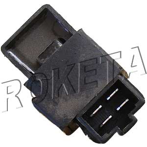
Also, I forgot to mention this earlier, there is an additional device on the electrical system that isn't on the schematics. It's called an Assistant Relay, and I have never seen one before. Do you by chance know what the Assistant Relay is responsible for doing? I have a picture of it below.

Jan 10, 2011 | 10:25 PM
#15
Thread Starter
|
Weekend Warrior
Joined: Dec 2010
Posts: 16
Likes: 0
From: Central, MA
I have no idea what this is. I did a google search and found your picture below and several others that all look like CDI's. I'm continuing to look into this....
What color wires plug into this device?
Have you found your CDI? According to the wiring diagram you provided it is a two connector six pin CDI. Is this correct?
What color wires plug into this device?
Have you found your CDI? According to the wiring diagram you provided it is a two connector six pin CDI. Is this correct?
I have indeed located my CDI. It's a 2 connector with 6 pins, same as the one pictured in my first post. The Assistant Relay has 3 pins, Pink, Maroon and Black, all solid with no stripes. After attempting to follow the wires, it seems that the pink wire goes to the clutch diode. I will begin the voltmeter readings now.
Jan 10, 2011 | 10:50 PM
#16
Electrical Expert
Likes High Voltage In The Tub!
Likes High Voltage In The Tub!
Joined: Dec 2008
Posts: 3,260
Likes: 14
From: Tracy, California, USA
Nope. The magnet that generates the trigger voltage is inside the trigger coil itself. That raised bump on the flywheel bends the magnetic field inside the trigger coil this way and that in close flyby using the magnet in the trigger coil itself. It's the leading and trailing edge of the bump that generates the trigger plus/minus voltage spikes. This is done this way to keep the magnets from the battery charge windings and CDI power winding from affect the trigger signal.
Jan 10, 2011 | 10:54 PM
#17
Thread Starter
|
Weekend Warrior
Joined: Dec 2010
Posts: 16
Likes: 0
From: Central, MA
Nope. The magnet that generates the trigger voltage is inside the trigger coil itself. That raised bump on the flywheel bends the magnetic field inside the trigger coil this way and that in close flybyusing the magnet in the trigger coil itself. Its the leading and trailing edge of the bump that generates the trigger plus/minus voltage spikes. This is done this way to keep the magnets from the battery charge windings and CDI power winding from affect the trigger signal.
1.)0 Ohms (with both grounds)
2.)Ignition on: No Reading(infinity?) / Ignition off: 2.3 Ohms
3.)312 Ohms
4.)312 Ohms
Jan 10, 2011 | 11:28 PM
#18
Thread Starter
|
Weekend Warrior
Joined: Dec 2010
Posts: 16
Likes: 0
From: Central, MA
Nope. The magnet that generates the trigger voltage is inside the trigger coil itself. That raised bump on the flywheel bends the magnetic field inside the trigger coil this way and that in close flyby using the magnet in the trigger coil itself. It's the leading and trailing edge of the bump that generates the trigger plus/minus voltage spikes. This is done this way to keep the magnets from the battery charge windings and CDI power winding from affect the trigger signal.
5.)2.7 ohms
6.)46 volts
7.).23 volts
8.)NO zeros, constant .040-.101 volts reading
 Jan 10, 2011 | 11:33 PM
#19
Thread Starter
|
Weekend Warrior
Joined: Dec 2010
Posts: 16
Likes: 0
From: Central, MA
Almost forgot to mention, the previous owner removed the ENTIRE rear brake assembly due to a leaking seal  So there is nothing to close the circuit for the rear brake light. I wouldn't think that would be the issue, but I have seen crazier things occur.
So there is nothing to close the circuit for the rear brake light. I wouldn't think that would be the issue, but I have seen crazier things occur.
Jan 12, 2011 | 12:12 AM
#20
Electrical Expert
Likes High Voltage In The Tub!
Likes High Voltage In The Tub!
Joined: Dec 2008
Posts: 3,260
Likes: 14
From: Tracy, California, USA
From the wiring diagram I see that the quad does not use the common brake safety interlock to keep the starter from turing unless the brakes are applied. Instead it uses the neutral switch and/or the clutch switch to keep the starter from turning in a condition where it could take off unexpectedly.
There is a mistake in the diagram you posted. The starter solenoid in the diagram is wired to the wrong side of the clutch diode. The pink wire from the solenoid should be wired to the pink wire from the clutch switch (and clutch diode), not the way the diagram shows. The way the diagram shows cannot possibly work. No matter - this has nothing to do with spark.
Your assistant relay is wired into the clutch diode pink wire. The black wire is most likely switched 12 volts from the ignition switch. I don't know what it does yet. Look at all your quad connectors in the wiring harness. Is there a maroon wire anywhere? If so, what does this color wire connect to?
Your test results:
3) and 4) are suspicious. It is very unlikely that the ignition power winding in the stator is exactly tthe same resistance and the trigger voltage winding. You may want to recheck that.
5) This resistance is really high. Mine reads 0.3 ohms. This is suspicious.
8) This looks suspicious. It doesn't look like your CDI is putting out anything like the right voltages. Note that this pin looks suspicious and two counts. The coil resistance readings look high and the output voltage is wrong.
The rest of the readings look OK. The trigger voltage looks normal, and the AC ignition power voltage looks normal. What this says is that the stator is outputting the proper voltages from the power and trigger windings. But this doesn't match up with your resistance readings from the same two windings (3) and 4)). Something is not right. It would be worthwhile to remeasure these and see if we can get these readings to agree with each other and then maybe point the same way...
If your wiring diagram is accurate (well mostly accurate anyway) then your quad doesn't use the brake switch for any interlocks - starter motor or spark.