
no fire on chinses 110cc atv
 Sep 22, 2011 | 04:15 AM
#11

Thread Starter
|
Weekend Warrior
Joined: Sep 2011
Posts: 8
Likes: 0
Hi Lynn ok then my problem is the stator a bad one for a bad one lol I put the old one in anyway and measured the black/red it gave me 2.8 volts ac and zero on trigger I'll poke around in the old one to try to fix and maybe remove the trigger coil from the old one and put it on the new one maybe with two I can make one thanks alot Lynn I'll let you know what happened
Sep 22, 2011 | 10:49 PM
#12

Electrical Expert
Likes High Voltage In The Tub!
Likes High Voltage In The Tub!
Joined: Dec 2008
Posts: 3,260
Likes: 14
From: Tracy, California, USA
Hi Lynn ok then my problem is the stator a bad one for a bad one lol I put the old one in anyway and measured the black/red it gave me 2.8 volts ac and zero on trigger I'll poke around in the old one to try to fix and maybe remove the trigger coil from the old one and put it on the new one maybe with two I can make one thanks alot Lynn I'll let you know what happened
This suggests there may still be a problem with the way the trigger voltage is being measured. It is unlikely that your first stator had a "double failure" where both the trigger winding *and* the Ignition power winding failed at exactly the same. They would have had to fail at the same time since either one, if it failed first, would have killed the ignition system and stopped the quad dead in its tracks. You've only had a few minutes of cranking time after that - not likely enough "run" time to statistically rack up a second failure. I hope my logic is making sense here... I think we're not out of the woods yet...
There's no harm in poking around inside the bad stator. If you do decide to try and swap the trigger coils (assuming it's even possible) note that the clearance between the trigger coil and the raised bump on the flywheel that passes underneath it is important. I'd set it at about 0.025".
Sep 23, 2011 | 03:57 AM
#13
Thread Starter
|
Weekend Warrior
Joined: Sep 2011
Posts: 8
Likes: 0
Ok here this is how it went from day one when I first changed the csi box I cranked and had spark so then put the plug back in got it started let run for a little while then I put everything back together and started it up again I went for a ride maybe about 500 feet and then it died back in garage check for spark and no more spark and now we are here lol yes I changed the coils easy it has a welded jointat the bottom so heat up the joint remove the wire and reweld th other coil same way put it back in and still nothing 0.01 volts ac I don 't see how you gap it seeing how it goes screwed in once in it does not move I think I'll buy another stator it was only 19 dollars I'll let you know
Oct 8, 2011 | 10:00 PM
#15
Electrical Expert
Likes High Voltage In The Tub!
Likes High Voltage In The Tub!
Joined: Dec 2008
Posts: 3,260
Likes: 14
From: Tracy, California, USA
You have a new stator so you need to do all of the tests again since its a new ball game. 0.3 volts on the trigger wire looks OK if and only if you have the proper resistance too. You're going to need to do all the measurements again. Sorry...  There are no shortcuts in electronics, and you have to be painstakenly accurate. That is why I think a lot of otherwise very intelligent people have difficulties when working with electrical stuff
 ")
Here again is the generic procedure for an AC powered 5 pin CDI:
There are no shortcuts in electronics, and you have to be painstakenly accurate. That is why I think a lot of otherwise very intelligent people have difficulties when working with electrical stuff Here again is the generic procedure for an AC powered 5 pin CDI:
Is this a picture of your CDI?
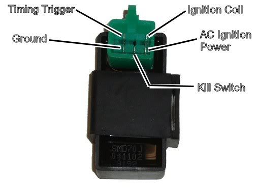
Assuming the answer is yes, the first thing to do is eliminate all kill switches and kill switch wiring:
Method 1) Unplug the CDI and remove the kill switch pin in the CDI connector on the wiring harness. The pin is held in with a spring tab on the pin itself. You'll have to probe into the connector and push this tab in order to extract the pin. Plug the CDI back in (kill switch wire dangling) and see if you have spark.
Method 2) Unplug the CDI. Turn on the ignition switch and set all kill switches to the run position. Use a meter to measure resistance in of the kill switch pin in the wiring harness connector to engine/frame ground. If the reistance is infinite on the 100K ohm scale then your kill switches/kill switch wiring are OK. If you measure zero ohms then you have a kill switch/wiring issue.
The other inputs your CDI needs to make spark are AC Ignition Power, and the Trigger signal. Do the following:
1) Unplug the CDI. In the wiring connector measure the resistance of the AC Ignition Power pin to the Ground pin. You should see 400 ohms or so. What do you measure?
2) Measure the resistance of the Timing/trigger pin to the ground pin. You should measure 150 ohms or so. What do you measure?
3) Leave the CDI unplugged. Set your meter to measure AC volts on the 100 volt scale. Measure the voltage on the AC Ignition Power pin to the ground pin while cranking the engine. You should see 40 to 80 volts AC while the engine is cranking. What do you measure?
4) Set your meter to measure AC volts on the lowest scale you have. Ideally this would be 2 volts but many meters don't go down this low. In that case use the lowest scale you have. Measure the voltage on the Timing Trigger pin to the Ground pin while cranking the engine. You should 0.2 t0 0.4 volts AC. What do you measure?
Now for measuring the output side of the CDI:
A) Leave the CDI unplugged. In the CDI wiring connector measure the resistance of the Ignition Coil pin to the ground pin. You should measure less than 1 ohm (but not zero ohms). What do you measure?
B) Plug the CDI back in. Set your meter to measure AC volts on the 20 volt scale. Set all kill switches to the run position. Crank the engine while measuring the voltage on the Igntition Coil pin to ground. Poke through the insulation of the wire if you can't probe the connector.
Caution: There should be moderately high voltage spikes on this wire. Make sure your fingers are not part of the circuitry. Don't touch the probe lead tips while doing this test.
What you should see is a lot of random numbers with lots of zero values as well. This is because the meter may catch all or part of the spark event voltage, with a lot of nothing in between. Describe what you see.
Note: Using a meter to measure this point produces highly variable results depending on the meter. What you really need is an oscilloscope, but most always a meter is all that is available. We have to do the best we can with what's available. Describe the meter results as accurately as you can - there is information there to chew on....
Oct 31, 2011 | 02:48 PM
#16

Weekend Warrior
Joined: Oct 2011
Posts: 6
Likes: 0
I did all the checks that you drew out in the last post. The only thing that checked out was the kill switches did not zero out. I don't have any voltage on anything at anytime. is it a bad Magneto? Stator?
I have power to the starter and the engine cranks just no spark.
I have power to the starter and the engine cranks just no spark.

Thread
Thread Starter
Forum
Replies
Last Post
mrtidy
Polaris Ask an Expert! In fond memory of Old Polaris Tech.
9
Feb 3, 2016 05:00 PM
IMLN
Polaris Ask an Expert! In fond memory of Old Polaris Tech.
2
Sep 28, 2015 03:32 PM
Elkaholic
Land, Trail and Environmental Issues
1
Sep 6, 2015 02:44 PM
Currently Active Users Viewing This Thread: 1 (0 members and 1 guests)