
atv 150cc stator testing no spark
 Nov 16, 2011 | 06:52 PM
#1

Thread Starter
|
Weekend Warrior
Joined: Nov 2011
Posts: 10
Likes: 0
HI ALL.I have read some of the other post, still need help. Lynn i see you are a very helpful person,maybe you can help me.I picked up this baja atv 150cc with no spark. The stator wires has a plug with 3 wires and 1 loose wire. The wire color at the plug are, gr,w,y. 1 loose wire is bl/y.With your test check while cranking ac my y to w = 5.7 then said b/w mine is b/y to ground= 00.1 did i do it right? that would be a bad stator?
with meter set at 200 omhs not cranking gr to ground = 19.3 with different ground goes higher up to 200.
b/y to green = 131.7 and b/y to ground right around 150.0
what do you think so far. i thank you for your help. by the way nice site.
thanks guys.
with meter set at 200 omhs not cranking gr to ground = 19.3 with different ground goes higher up to 200.
b/y to green = 131.7 and b/y to ground right around 150.0
what do you think so far. i thank you for your help. by the way nice site.
thanks guys.
Nov 17, 2011 | 12:21 AM
#2

Electrical Expert
Likes High Voltage In The Tub!
Likes High Voltage In The Tub!
Joined: Dec 2008
Posts: 3,260
Likes: 14
From: Tracy, California, USA
The Blue/Yellow loose wire is the timing trigger wire to the CDI.
The White, Yellow wires are for charging your battery through the voltage regulator. This has nothing to do with spark, and so these wires can be ignored for this particular problem.
Green is ground.
But I'm not understanding the "then said b/w mine is b/y to ground= 00.1 did i do it right?" statement at all. Could you rephrase that?

What resistance do you measure between the negative battery terminal and the quad frame? Be sure to dig into bare metal through any paint with your meter probes.
What is the resistance between the negative battery terminal and the engine block. Again be sure to dig in with the probes and get a good connection.
Try measuring the resistance from the negative battery terminal to any other ground you can find. They should all read zero ohms. Any "ground" resistance that is not really close to zero is bad, and that is a wire connection problem that needs to be looked at closely...
Nov 17, 2011 | 11:43 AM
#3
Thread Starter
|
Weekend Warrior
Joined: Nov 2011
Posts: 10
Likes: 0
Your missing a Blk/red wire which is normally the AC Ignition Power wire. That suggests your CDI is DC powered and *not* AC powered.
missing it or this model does not have it ?
What resistance do you measure between the negative battery terminal and the quad frame? Be sure to dig into bare metal through any paint with your meter probes.
cleaned frame with a file 00.2
What is the resistance between the negative battery terminal and the engine block. Again be sure to dig in with the probes and get a good connection.
00.2 cleaned with file
Try measuring the resistance from the negative battery terminal to any other ground you can find. They should all read zero ohms. Any "ground" resistance that is not really close to zero is bad, and that is a wire connection problem that needs to be looked at closely...
i cleaned some connections.and have no history of the thing only wont start.
if i touch probes together i get 00.2
wires at stator,unplugged
green to ground 00.2
blu/y to ground 131.3
blu/y to green 132.00
i thank you for your time
Nov 17, 2011 | 02:46 PM
#4
Thread Starter
|
Weekend Warrior
Joined: Nov 2011
Posts: 10
Likes: 0
hello again, thought i found problem.pulled stator out the blu/y wire was pinched bare wire. put meter on the ends of blu/y reading of 00.2 .then one wire on end of blu/y to the tigger mounting bracket goes up to 135.0
so is trigger shorted??
can u buy just the trigger?
i see whole stator online with bk/red wire,just dont use it?
thanks again
so is trigger shorted??
can u buy just the trigger?
i see whole stator online with bk/red wire,just dont use it?
thanks again
Nov 18, 2011 | 12:22 AM
#5
Electrical Expert
Likes High Voltage In The Tub!
Likes High Voltage In The Tub!
Joined: Dec 2008
Posts: 3,260
Likes: 14
From: Tracy, California, USA
 . Making good repeatable measurements is a skill that requires practice...
I'm assuming you have a DC powered 6 pin CDI. Here is the generic procedure for no spark problems on these CDI's...
When doing these tests please do *all* of them and report back *all* the values. Each piece of information is important. Some of the tests reinforce each other, or if they don't, point to measurement issues (as for example your last post).
To troubleshoot no spark problems on a 6 pin DC powered CDI it makes sense to start in the middle (the CDI), measure as much as we can and branch out from there. For the CDI to do its thing it needs power, a trigger pulse, and it must not be inhibited via the kill switch input pin.
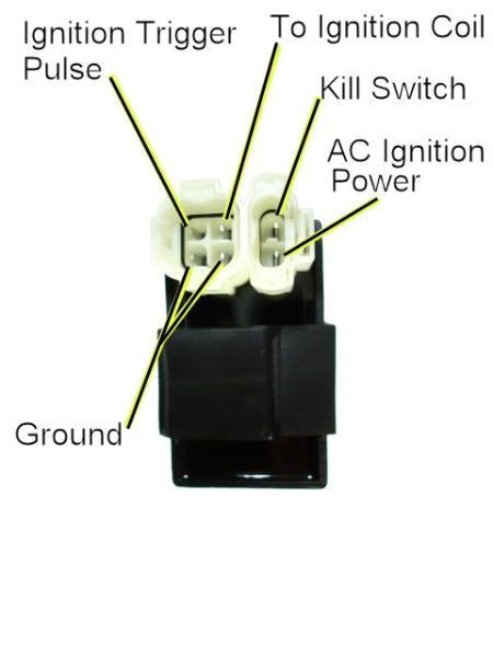
1) Unplug the CDI. Turn the ignition switch on. Set all kill switches the the "run" position. In the wiring harness, look to see if you have a wire on the kill switch pin. If you do, measure the resistance of the kill switch pin to the ground pin on the 20K ohm scale. It should read infinite ohms (same as when the meter leads are hanging free and not touching anything). It should not read zero ohms (shorted).
2) Leave the CDI unplugged, and the ignition switch in the "on" position. Use a meter to measure the DC voltage on the pin labeled "AC ignition power" in the wiring harness to the ground wire on the 2K ohm scale. You should read battery voltage (12 volts). What do you measure?
3) Leave the CDI unplugged. Use a meter to measure the resistance of the "Ignition Trigger Pulse" pin in the wiring harness to the ground wire on the 2K ohm scale. You should read approximately 150 ohms. What do you measure?
4) Set your meter down to the lowest scale you have for measuring AC volts. 2 volts would be ideal, but some meters don't go that low. In that case use the lowest scale you have. While cranking the engine, measure the voltage on the Ignition Trigger Pulse pin in the wiring harness to the ground pin. You should measure 0.2 to 0.5 volts AC. What do you measure?
5) Now plug the CDI back in. Measure the AC voltage on the Ignition Coil pin to the ground pin using the 200 volt scale. If you have to, use a sewing pin to poke through the wire insulation and then put the meter probe on the sewing pin. But don't hold your fingers on the connection during the next test - there may be high voltage here when the engine is turning. With the ignition on and all kill switches set to the "run" position, crank the starter motor. You should see voltages bouncing around at random values and the meter captures all or part of a spark event. What do you see?
Nov 18, 2011 | 12:33 AM
#6
Electrical Expert
Likes High Voltage In The Tub!
Likes High Voltage In The Tub!
Joined: Dec 2008
Posts: 3,260
Likes: 14
From: Tracy, California, USA
hello again, thought i found problem.pulled stator out the blu/y wire was pinched bare wire. put meter on the ends of blu/y reading of 00.2 .then one wire on end of blu/y to the tigger mounting bracket goes up to 135.0
so is trigger shorted??
can u buy just the trigger?
i see whole stator online with bk/red wire,just dont use it?
thanks again
so is trigger shorted??
can u buy just the trigger?
i see whole stator online with bk/red wire,just dont use it?
thanks again
You usually cannot even remove the trigger coil from the stator chassis. It is welded down on most stators. The clearance between the coil and the raised steel bump on the flywheel is critical BTW.
Make sure if you get a new stator (not my recommendation at this point) to get one with the same number of poles. Many 150cc quads have a six pole stator. Others have eight poles. The number of poles on the stator must match the number of magnets embedded in the flywheel of the battery charge circuitry will not work at all.
Yes, if you get a stator with the red/blk wire you can just leave it disconnected.
Nov 18, 2011 | 05:50 PM
#7
Thread Starter
|
Weekend Warrior
Joined: Nov 2011
Posts: 10
Likes: 0
hi,i did answer all your questions,when i quote your questions i did not change the ink color for my answers. sorry. maybe we can start over fresh, i will report back with answers to your questions.i will test it on saturday. thank you for the help.
i have a 4 pin cdi, a green, bk/r ,bk/y , and bk/w wires.
thank you, pete
i have a 4 pin cdi, a green, bk/r ,bk/y , and bk/w wires.
thank you, pete
Trending Topics
Nov 18, 2011 | 11:05 PM
#8
Electrical Expert
Likes High Voltage In The Tub!
Likes High Voltage In The Tub!
Joined: Dec 2008
Posts: 3,260
Likes: 14
From: Tracy, California, USA
Yes maybe starting over may be a good idea because I'm a bit confused
You have a four pin CDI on a 150cc machine? If so this is a first for me, though a suppose there is no reason why it couldn't be...
Does your 4 pin CDI look like this?
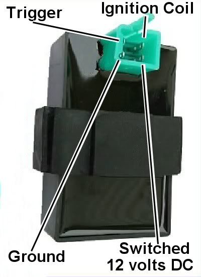
Another thing that doesn't add up is your blue/yellow wire from the stator should go to your timing trigger input to the CDI. Yet you don't have a blue/yellow wire at your CDI. Hmmm..
What model Baja do you have? I'll see if I can find a published wiring diagram.
When I was asking for you to do *all* of the tests I was referring to the next set of tests with the six pin CDI - not your previous tests.
We'll get to the bottom of this... We just might need to make a few meter measurements to figure out what ignition configuration you have...
You have a four pin CDI on a 150cc machine? If so this is a first for me, though a suppose there is no reason why it couldn't be...
Does your 4 pin CDI look like this?
Another thing that doesn't add up is your blue/yellow wire from the stator should go to your timing trigger input to the CDI. Yet you don't have a blue/yellow wire at your CDI. Hmmm..
What model Baja do you have? I'll see if I can find a published wiring diagram.
When I was asking for you to do *all* of the tests I was referring to the next set of tests with the six pin CDI - not your previous tests
.We'll get to the bottom of this... We just might need to make a few meter measurements to figure out what ignition configuration you have...
Nov 19, 2011 | 01:13 PM
#9
Thread Starter
|
Weekend Warrior
Joined: Nov 2011
Posts: 10
Likes: 0
Yes maybe starting over may be a good idea because I'm a bit confused
You have a four pin CDI on a 150cc machine? If so this is a first for me, though a suppose there is no reason why it couldn't be...
Does your 4 pin CDI look like this?
yes, and wired the same.
Another thing that doesn't add up is your blue/yellow wire from the stator should go to your timing trigger input to the CDI. Yet you don't have a blue/yellow wire at your CDI. Hmmm..
my bl/y from stator turns into bk/w going to cdi
What model Baja do you have? I'll see if I can find a published wiring diagram.
only said baha 2006 149.5 cc quad
When I was asking for you to do *all* of the tests I was referring to the next set of tests with the six pin CDI - not your previous tests.
ok
We'll get to the bottom of this... We just might need to make a few meter measurements to figure out what ignition configuration you have...
You have a four pin CDI on a 150cc machine? If so this is a first for me, though a suppose there is no reason why it couldn't be...
Does your 4 pin CDI look like this?
yes, and wired the same.
Another thing that doesn't add up is your blue/yellow wire from the stator should go to your timing trigger input to the CDI. Yet you don't have a blue/yellow wire at your CDI. Hmmm..
my bl/y from stator turns into bk/w going to cdi
What model Baja do you have? I'll see if I can find a published wiring diagram.
only said baha 2006 149.5 cc quad
When I was asking for you to do *all* of the tests I was referring to the next set of tests with the six pin CDI - not your previous tests
.ok
We'll get to the bottom of this... We just might need to make a few meter measurements to figure out what ignition configuration you have...
Nov 19, 2011 | 01:51 PM
#10
Thread Starter
|
Weekend Warrior
Joined: Nov 2011
Posts: 10
Likes: 0
hi, was having problem quoting your questions.
answers to your questions.
#1 no kill wire at cdi.
#2 12.38 dcv
#3 .043 ? 2k
#4 00.5 200 ac v
#5 00.0 ? 200 acv
on #3 if i release the brake handle, or if i unplug this black relay/breaker box the reading will go up to 130.the wires from bk box go to the starter solenoid and the brake switch. thanks