
Another chinese no spark
 Jan 26, 2012 | 11:24 PM
#11

Electrical Expert
Likes High Voltage In The Tub!
Likes High Voltage In The Tub!
Joined: Dec 2008
Posts: 3,260
Likes: 14
From: Tracy, California, USA
I've been answering posts on quad electrical problems for a long time time now. One thing I've noticed is that on average the questions are getting a lot tougher as time goes on. I hope that this is because 90% of the problems are getting solved via search engines and previous posts. The alternative is that I'm getting dumber  .
.
There is still the issue that you have a very small trigger voltage, but it is not zero. It looks like the CDI is not getting triggered or is bad - yet you've changed the CDI.... You have plenty of AC power to the CDI. You verified the kill switch connection is open. So all the inputs to the CDI are OK except perhaps the trigger voltage. But the output is not right. So try as we might we are in the same quandry with a marginal trigger voltage...
We could change the stator, or try making this simple fixture:
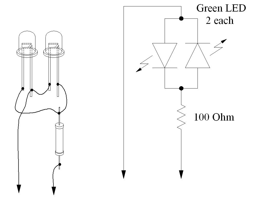
If you plug this fixture onto the trigger signal and ground pins at the CDI connector you should see both LEDs (light emitting diodes) flash at about 10 times per second while cranking. If you do see the falshes you definately have sufficient trigger voltage. Then you're looking at something really bizzarre - but at least we can eliminate the stator trigger signal.
The picture specifies green LEDs but any color will work. The two LEDs are mounted back to back so that one will flash on the negative portion of the trigger waveform, and the other will flash on the positive. All these parts are available cheaply at Radio Shack (or any electronics store).
Here is the actual waveform that you would see if you had an oscilloscope to plot the instantaneous voltage versus time:
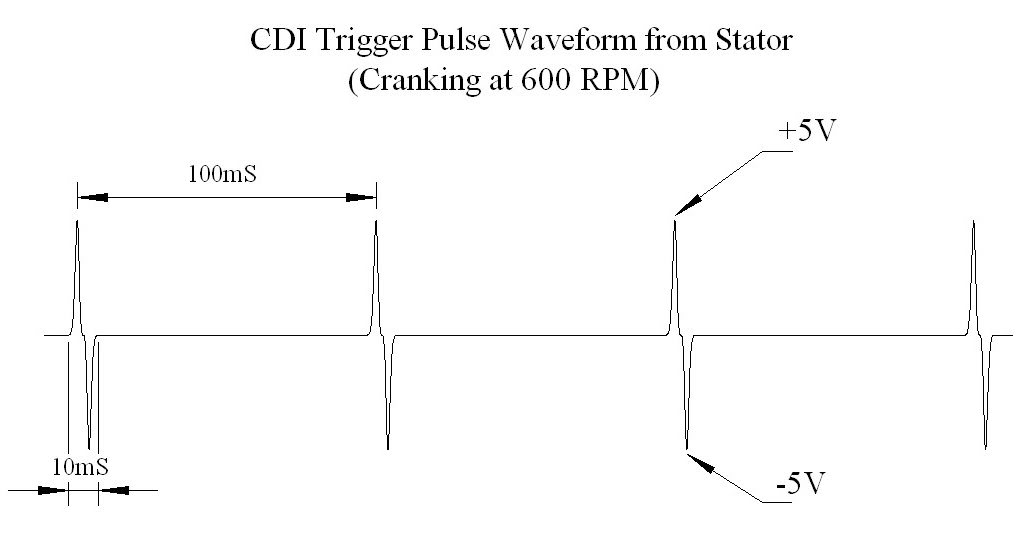
Note the very narrow pulses and the low duty cycle. The low duty cycle causes the meter to average the sharp pulses with lots of zero volts inbetween - hence the low reading on most meters.
.There is still the issue that you have a very small trigger voltage, but it is not zero. It looks like the CDI is not getting triggered or is bad - yet you've changed the CDI.... You have plenty of AC power to the CDI. You verified the kill switch connection is open. So all the inputs to the CDI are OK except perhaps the trigger voltage. But the output is not right. So try as we might we are in the same quandry with a marginal trigger voltage...
We could change the stator, or try making this simple fixture:
If you plug this fixture onto the trigger signal and ground pins at the CDI connector you should see both LEDs (light emitting diodes) flash at about 10 times per second while cranking. If you do see the falshes you definately have sufficient trigger voltage. Then you're looking at something really bizzarre - but at least we can eliminate the stator trigger signal.
The picture specifies green LEDs but any color will work. The two LEDs are mounted back to back so that one will flash on the negative portion of the trigger waveform, and the other will flash on the positive. All these parts are available cheaply at Radio Shack (or any electronics store).
Here is the actual waveform that you would see if you had an oscilloscope to plot the instantaneous voltage versus time:
Note the very narrow pulses and the low duty cycle. The low duty cycle causes the meter to average the sharp pulses with lots of zero volts inbetween - hence the low reading on most meters.
Feb 4, 2012 | 09:03 AM
#13

Thread Starter
|
Weekend Warrior
Joined: Jan 2012
Posts: 8
Likes: 0
I built the fixture you suggested but did not see the flashes, I was in bright sunlight, I know the led's worked because I hooked them to a battery.
When switching polarity the led's would alternate lighting.
Anyway a friend of mine suggested holding the wire going to the coil from cdi close to ground screw and check for spark and it sparked! I figured it must be the coil or sparkplug wire. Order new one and got spark. Now I have carb issues which I hopefully can resolve.
Lynn, many thanks for your time and help, you provide a great service to us diy guys.
Feb 7, 2012 | 11:29 PM
#14
Electrical Expert
Likes High Voltage In The Tub!
Likes High Voltage In The Tub!
Joined: Dec 2008
Posts: 3,260
Likes: 14
From: Tracy, California, USA
I'm glad you got it working  .
.
I probably should have explained a little more about how that LED fixture works. LEDs (light emitting diodes) will not conduct in the reverse direction at all (assuming you keep the voltages within reason). In the forward direction they will conduct freely only after you exceed the forward barrier voltage (and then emit light too). For LEDs (made from gallium arsenide) this barrier voltage is around 2 volts, so if the LEDs light up at all (even if faintly) you know the stator is putting out more than 2 volts - which is enough to trigger the CDI. They will glow much fainter hooked to the stator than when hooked across a battery because the battery is putting out *12 volts all the time*, while the stator is just putting out *very brief 5 volt* pulses. So looking in full sun could be problematic.
Rectifier diodes like the ones in your regulator rectifier are made from silicon instead of gallium arsenide and have a much lower forward barrier voltage (0.3 to 0.7 volts).
I don't quite understand the "holding the wire going to the coil from cdi close to ground screw " part. CDIs will not work at all with coil primary disconnected since the CDI internal main storage capacitor charges through the coil primary winding. Regardless though, it is hard to fault success.
Let's hope it stays running well...
. I probably should have explained a little more about how that LED fixture works. LEDs (light emitting diodes) will not conduct in the reverse direction at all (assuming you keep the voltages within reason). In the forward direction they will conduct freely only after you exceed the forward barrier voltage (and then emit light too). For LEDs (made from gallium arsenide) this barrier voltage is around 2 volts, so if the LEDs light up at all (even if faintly) you know the stator is putting out more than 2 volts - which is enough to trigger the CDI. They will glow much fainter hooked to the stator than when hooked across a battery because the battery is putting out *12 volts all the time*, while the stator is just putting out *very brief 5 volt* pulses. So looking in full sun could be problematic.
Rectifier diodes like the ones in your regulator rectifier are made from silicon instead of gallium arsenide and have a much lower forward barrier voltage (0.3 to 0.7 volts).
I don't quite understand the "holding the wire going to the coil from cdi close to ground screw " part. CDIs will not work at all with coil primary disconnected since the CDI internal main storage capacitor charges through the coil primary winding. Regardless though, it is hard to fault success
.Let's hope it stays running well...
I built the fixture you suggested but did not see the flashes, I was in bright sunlight, I know the led's worked because I hooked them to a battery.
When switching polarity the led's would alternate lighting.
Anyway a friend of mine suggested holding the wire going to the coil from cdi close to ground screw and check for spark and it sparked! I figured it must be the coil or sparkplug wire. Order new one and got spark. Now I have carb issues which I hopefully can resolve.
Lynn, many thanks for your time and help, you provide a great service to us diy guys.
When switching polarity the led's would alternate lighting.
Anyway a friend of mine suggested holding the wire going to the coil from cdi close to ground screw and check for spark and it sparked! I figured it must be the coil or sparkplug wire. Order new one and got spark. Now I have carb issues which I hopefully can resolve.
Lynn, many thanks for your time and help, you provide a great service to us diy guys.


Thread
Thread Starter
Forum
Replies
Last Post
Currently Active Users Viewing This Thread: 1 (0 members and 1 guests)