
wiring diagram for kudaki 250cc
 Jul 3, 2012 | 02:29 PM
#1

Thread Starter
|
Weekend Warrior
Joined: Jul 2012
Posts: 11
Likes: 0
Hello. i recently got my hands on a kudaki 250 atv that has had an engine fire.
I dont really know much about this atv, so i cant find enough info on the internet.
Pics:
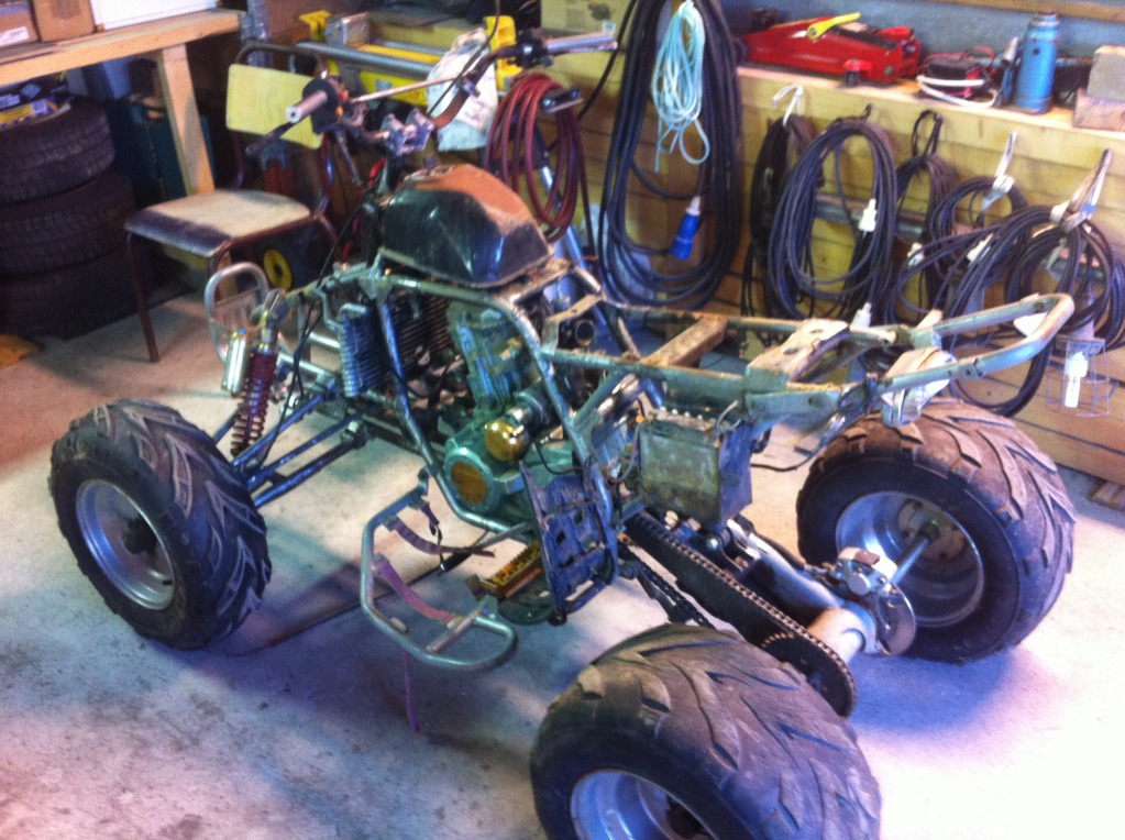
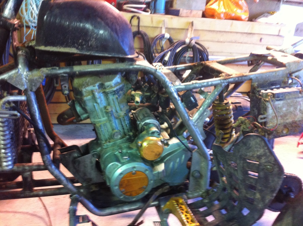
Im planning on rewiring it myself. I just need an related wiring diagram.
I dont know the buidyear, but i think its 2008/2009 or something like that.
I hope someone in here could help me with this. It would be much appreciated!
Best regards
Fredrik
I dont really know much about this atv, so i cant find enough info on the internet.
Pics:
Im planning on rewiring it myself. I just need an related wiring diagram.
I dont know the buidyear, but i think its 2008/2009 or something like that.
I hope someone in here could help me with this. It would be much appreciated!
Best regards
Fredrik
Jul 4, 2012 | 09:53 AM
#3
Extreme Pro Rider
Joined: Jun 2009
Posts: 3,224
Likes: 10
From: Texas
have you read some of Lynn Edwards' posts?
how many pins does your CDI have?
is it AC or DC? or do you know?
what color wires come out of the stator?
what color wires are on the regulator?
this is all critical information.
does it have a VIN stamped on the lower left hand part of the frame?
that'd tell us the year model.
how many pins does your CDI have?
is it AC or DC? or do you know?
what color wires come out of the stator?
what color wires are on the regulator?
this is all critical information.
does it have a VIN stamped on the lower left hand part of the frame?
that'd tell us the year model.
Jul 4, 2012 | 10:30 AM
#4
Thread Starter
|
Weekend Warrior
Joined: Jul 2012
Posts: 11
Likes: 0
have you read some of Lynn Edwards' posts?
how many pins does your CDI have?
is it AC or DC? or do you know?
what color wires come out of the stator?
what color wires are on the regulator?
this is all critical information.
does it have a VIN stamped on the lower left hand part of the frame?
that'd tell us the year model.
how many pins does your CDI have?
is it AC or DC? or do you know?
what color wires come out of the stator?
what color wires are on the regulator?
this is all critical information.
does it have a VIN stamped on the lower left hand part of the frame?
that'd tell us the year model.

the CDI has 6 pins.
Whats AC and DC?
Il find the colors of the wires tonight. Il check for the VIN too.
Thankyou for your respond. Is there any other information needed?
Jul 4, 2012 | 02:42 PM
#5
Thread Starter
|
Weekend Warrior
Joined: Jul 2012
Posts: 11
Likes: 0
Stator:
pink
black/red
blue/white
green/white
yellow
Regulator:
wires that comes out are in following order:
Yellow
red
red/white
yellow
green
I found this:
http://www.hooperimports.com/images/...diagram_HI.jpg
And its very simular to many of the wires. Could i use this to do the wiring?
pink
black/red
blue/white
green/white
yellow
Regulator:
wires that comes out are in following order:
Yellow
red
red/white
yellow
green
I found this:
http://www.hooperimports.com/images/...diagram_HI.jpg
And its very simular to many of the wires. Could i use this to do the wiring?
Jul 4, 2012 | 02:54 PM
#6
Extreme Pro Rider
Joined: Jun 2009
Posts: 3,224
Likes: 10
From: Texas
this is one of the common pics that Lynn Edwards uses in his replies concerning CDIs. in the chinese section of the forums, he also has a write up about identifying whether it is AC or DC. that's alternating current and direct current. like you car, alternating current. cars from the 40s-60s had direct current with the generators (even though some had alternators). more than likely, yours is AC....
once we identify what CDI you have and which pins are what, then tracing the wiring for termination will be made easier. then Lynn, who's the forum's electrical genius/expert, might have a simple wiring diagram to help you out PLUS his legendary advice. kudos to Lynn, he's the MASTER! either way, we'll help you get it back together.
 Jul 4, 2012 | 03:40 PM
#7
Thread Starter
|
Weekend Warrior
Joined: Jul 2012
Posts: 11
Likes: 0
Yes, i found this one earlier. And i think ive got all the wires to the CDI correct.
The one for the coil. ground, kill switch. and the two last one i got from the last wiring diagram i posted.
I also think i figgured out the whole startrelay to ignition to start switch thing,
But there is still some wires that dont match this diagram.
ive been wiring for some hours now and il do some reading later tonight. Il post pics too.
Thankyou for your help.
Trending Topics
Jul 4, 2012 | 04:53 PM
#8
Thread Starter
|
Weekend Warrior
Joined: Jul 2012
Posts: 11
Likes: 0
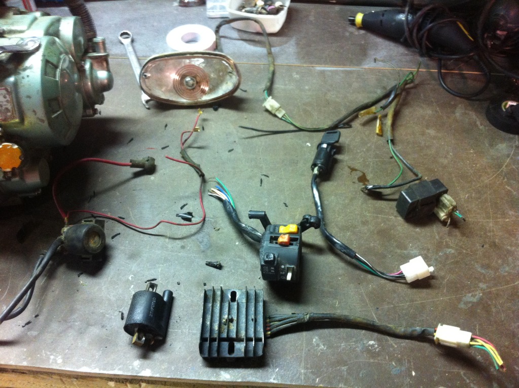
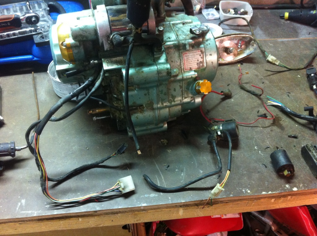
Ok i got some pics for explaining:
The components got a little cosmeticly damaged in the fire. but i think they work. Im also only using black, blue and red wires to rewire everything(because its all i got atm )
)
so it can be a little hard to see what goes where.
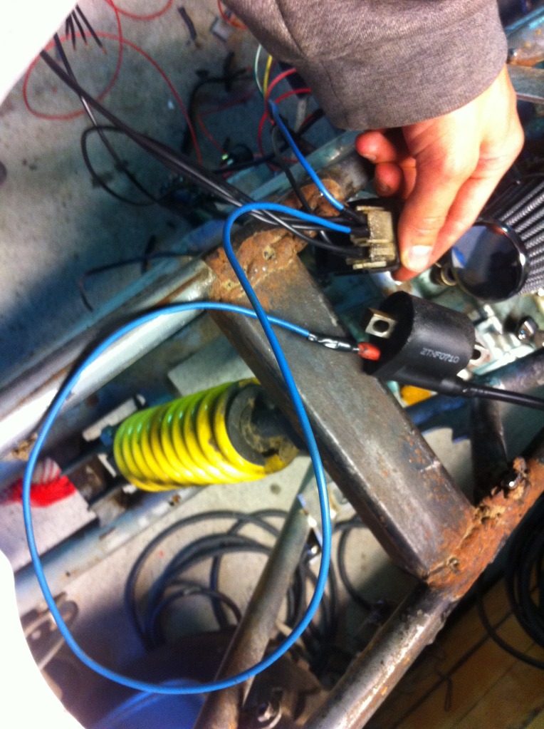
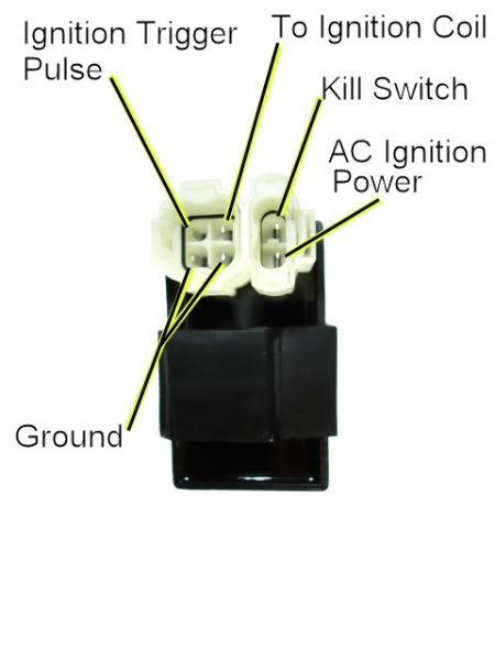
Here you can see i wired the + for the coil. going to "To ignition coil" on the CDI according to Lynn's pic.
Here you can see that i wired the Black/red wire from the stator to "AC ignition power" according to Lynn's pic.
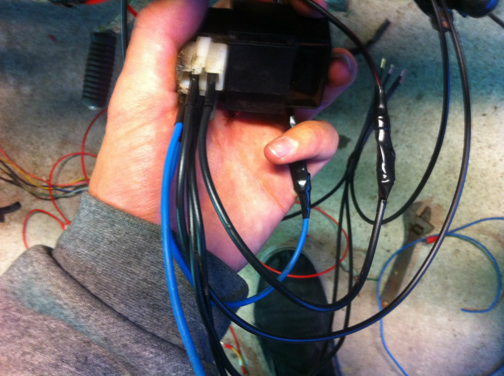
Here you can see that i wired the Blue/white wire from the stator to "Ignition trigger pulse" according to Lynns pic.
I also wired the two grounds. And made a kill switch leading to ground.
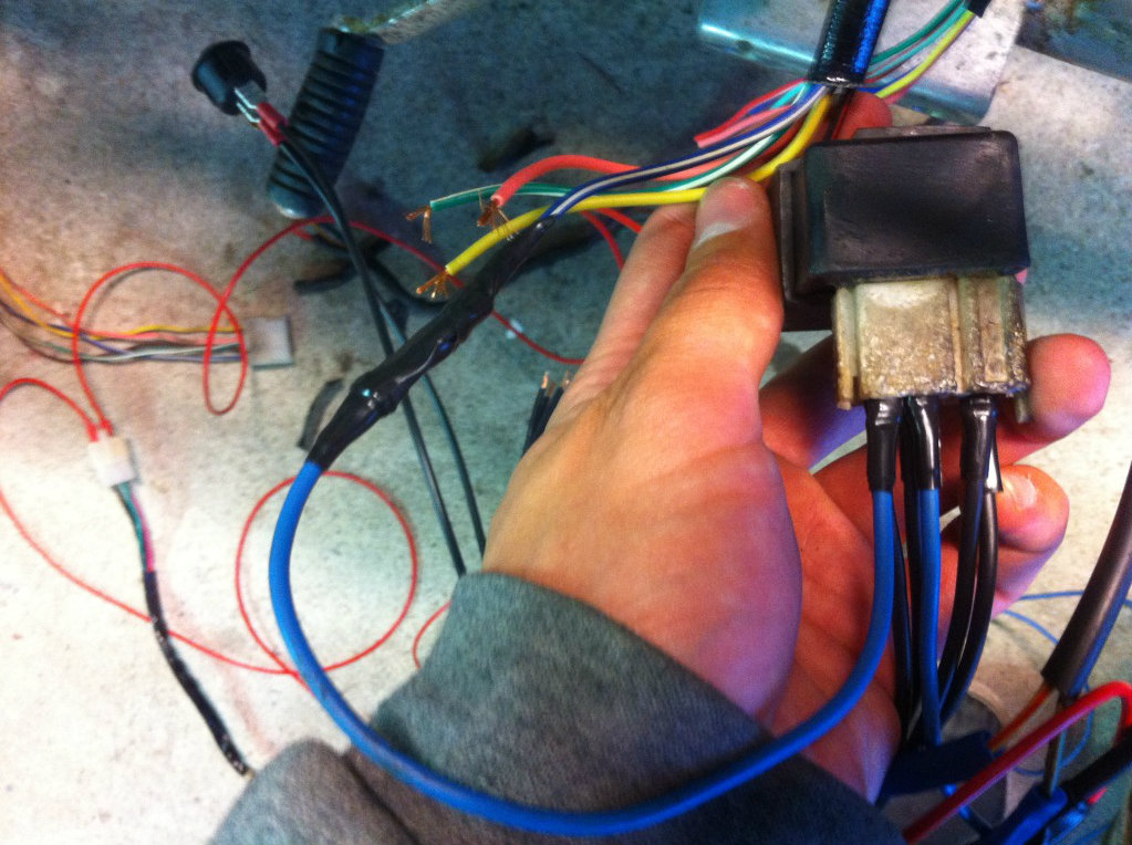
Here are the wires left coming from the stator:
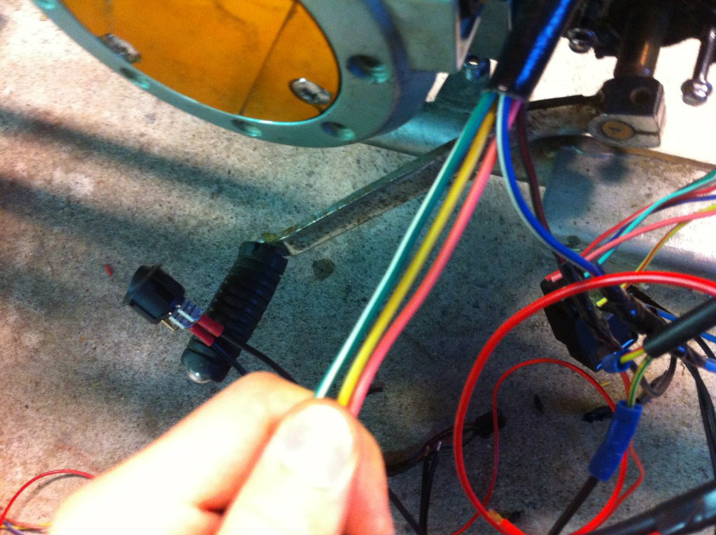
Green/white - yellow - pink
And here are the wires from the regulator:
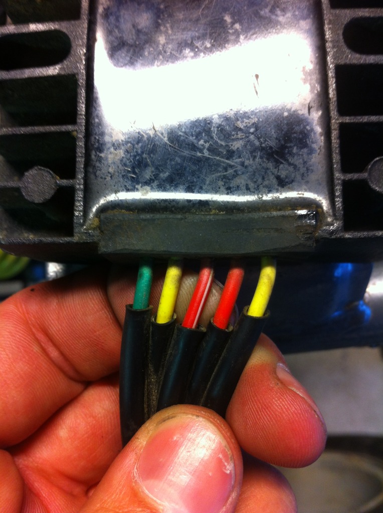
Green - yellow - red/white - red - yellow.
The regulator is the only thing i didnt wire according to this diagram:

The components got a little cosmeticly damaged in the fire. but i think they work. Im also only using black, blue and red wires to rewire everything(because its all i got atm
) so it can be a little hard to see what goes where.
Here you can see i wired the + for the coil. going to "To ignition coil" on the CDI according to Lynn's pic.
Here you can see that i wired the Black/red wire from the stator to "AC ignition power" according to Lynn's pic.
Here you can see that i wired the Blue/white wire from the stator to "Ignition trigger pulse" according to Lynns pic.
I also wired the two grounds. And made a kill switch leading to ground.
Here are the wires left coming from the stator:
Green/white - yellow - pink
And here are the wires from the regulator:
Green - yellow - red/white - red - yellow.
The regulator is the only thing i didnt wire according to this diagram:
Jul 4, 2012 | 10:33 PM
#9
Extreme Pro Rider
Joined: Jun 2009
Posts: 3,224
Likes: 10
From: Texas
now on your "used" wire and the wire you're replacing, you did check for continuity to test the integrity of each wire, correct? i'd hate for you to go through all of this, have a good feeling, hook it up and BAM, not make contact somewhere only to find out one of the "used" wires is pulled in half under the wire jacket. just my two cents.
Jul 4, 2012 | 11:11 PM
#10

Electrical Expert
Likes High Voltage In The Tub!
Likes High Voltage In The Tub!
Joined: Dec 2008
Posts: 3,260
Likes: 14
From: Tracy, California, USA
I'm really behind in posts. I wanted to reply much earlier but I've been running out of time. Besides, Jaster94 input has been very good.
I don't see anything wrong with your wiring diagram other than there is no safety starter interlock that keep the quad from being started up in gear with the brakes off. This would be the equivalent of wiring a car that can be started up in drive. Think about it. I'm fine with this as long as you are aware of the possible negative outcomes, and are willing to take responsibility for them.
I also don't see a fuse. You *absolutely* need a fuse off the positive battery terminal feeding everything other than the heavy gauge wires feeding the starter motor through the startor solenoid. 10 amps is a good value. You don't want another fire, right? Even if your previous fire was gasoline related, electrical fires can be pretty spectacular too. Fuses are there to prevent that.
I don't see anything wrong with your wiring diagram other than there is no safety starter interlock that keep the quad from being started up in gear with the brakes off. This would be the equivalent of wiring a car that can be started up in drive. Think about it. I'm fine with this as long as you are aware of the possible negative outcomes, and are willing to take responsibility for them
.I also don't see a fuse. You *absolutely* need a fuse off the positive battery terminal feeding everything other than the heavy gauge wires feeding the starter motor through the startor solenoid. 10 amps is a good value. You don't want another fire, right? Even if your previous fire was gasoline related, electrical fires can be pretty spectacular too. Fuses are there to prevent that
.