When you click on links to various merchants on this site and make a purchase, this can result in this site earning a commission. Affiliate programs and affiliations include, but are not limited to, the eBay Partner Network.
I have a GY6 moped, standard chinese junk. Brand new parts. The wire harness has standard color codes. Key is red to black on, green+b/w off (killswitch off ie killswitch is on when its off). There seems to be no power going to the wires. 12 volt signal is there on the red wire to b/w. Can I put the Red wire to B/w to start it? Since it has no amperage. I know the red to green is dangerous. But if I use the red to b/w? What will happen.
The GY6 engine is a circa 150cc four stroke and there is no colour standard for wiring mopeds or quads. A lot of Chinese makers use Honda's wiring colours of green for negative (earth), red for positive and black with white tracer for kill wire, but not all makers follow this code. If you put red (positive) to black & white, on a Honda set up, you will blow the CDI.
If anyone wants to bypass the safety switch/ ks and use key only, go from black to green/yellow and red to red/yellow. Don't touch the CDI switch. Then use a starter button.
After 3 days and heavy drinking, i managed to find a solution. This map here is the correct map.
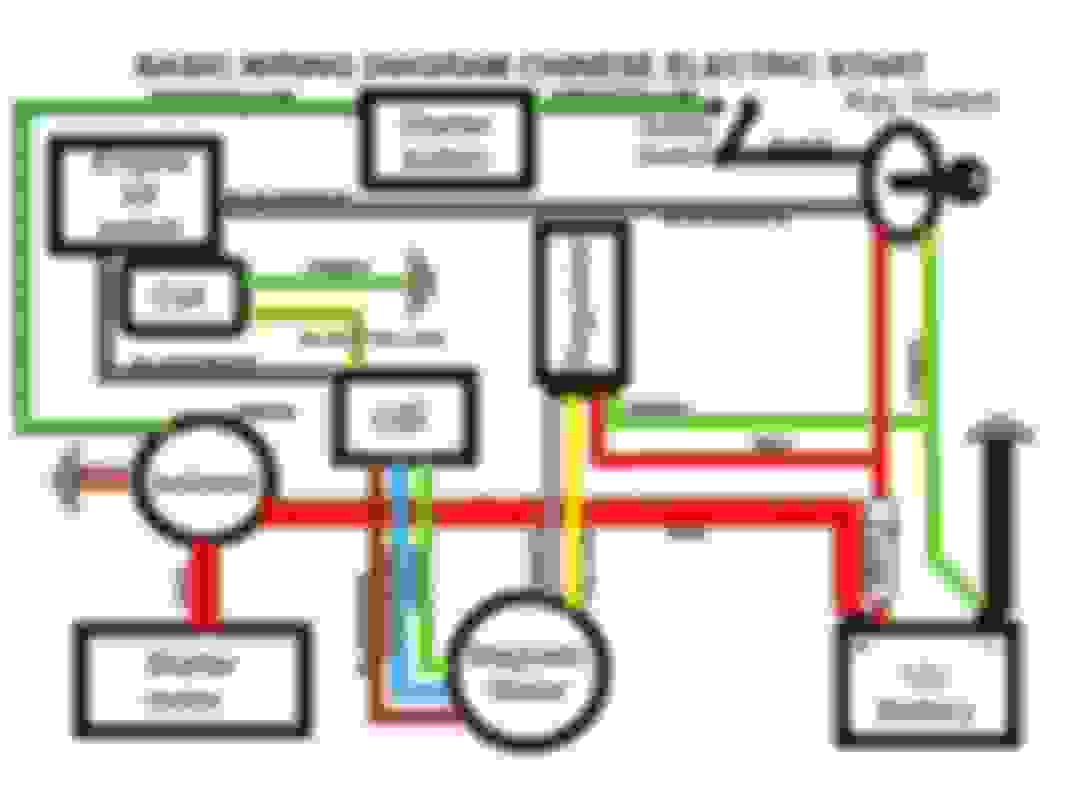
This map below that is posted all over the internet is trash:
What the creator did of this diagram was ultimately confuse me beyond repair. As you know, he does connect the solenoid to the ground. What this idiot did by making his diagram google searchable as an apparently easy to access wiring diagram, might infact confuse you to hell and back. The solenoid's red/Y wire infact needs to be grounded from the wire harness itself. Not from the solenoid's magical thin green wire that doesn't exist. The creator undoubtely made this wire into the solenoid's green/yellow wire.
A few years ago, I had the same confusion occur with my electromagnetic scooter...whom is just like a gas scooter except it replaces the cdi with standard capacitor, the dc rectifier with dc converted controller, the stator with a stationary 2 coil stator and the solenoid with a more powerful secondary battery unit. Hence I can atleast go cross country with an electric vehicle.
I just right now need to let every one know that the person of the chinese diagram named basic wiring diagram chinese electric start is either retarded or a basic liar. Good day.
BTW, I'm no mechanic but the diagram floating around the internet is an open circuit for the killswitch. I noted this as well as the major error on the solinoid. For some reason, I think 110ccs do not function in that way. By bypassing the killswitch, which is on the on position when off and off position when on, you are making a crucial mistake. The green to b/w wire will create a signal loss when the key is turned. The person whom made the original diagram is undoubtebly retarded. Thx.
Here's why:
Green- b/w key off (connection is made whilst ks is off ie the off posi of a ks is an open circuit)
Green- b/w key on is cut off (connection to the ks will still be available, and it will cut off the bike when the cdi is grounded)
I hope this helps to avoid retards on the internet.

 Dec 13, 2016 | 01:43 PM