
Meerkat 50 wiring problem
 Jul 24, 2008 | 02:03 AM
#21

Weekend Warrior
Joined: Jul 2008
Posts: 5
Likes: 0
Do you still have a copy of the wiring diagram for a 50 cc Meerkat? Can anyone help?
My e-mail is aardemaelectric@yahoo.com
Thank you.
My e-mail is aardemaelectric@yahoo.com
Thank you.
Jul 24, 2008 | 02:17 PM
#22

Range Rover
Joined: Jun 2008
Posts: 128
Likes: 0
<div class="FTQUOTE"><begin quote>Originally posted by: paardema
Do you still have a copy of the wiring diagram for a 50 cc Meerkat? Can anyone help?
My e-mail is aardemaelectric@yahoo.com
Thank you.</end quote></div>
no problem just look under smb05 posts,its 5 postings up and click on the meerkat 50 wiring diagram. then print it out.
Do you still have a copy of the wiring diagram for a 50 cc Meerkat? Can anyone help?
My e-mail is aardemaelectric@yahoo.com
Thank you.</end quote></div>
no problem just look under smb05 posts,its 5 postings up and click on the meerkat 50 wiring diagram. then print it out.
Jul 26, 2008 | 03:44 AM
#23

Weekend Warrior
Joined: Jul 2008
Posts: 1
Likes: 0
 Dec 2, 2010 | 10:17 AM
#27

Weekend Warrior
Joined: Dec 2010
Posts: 3
Likes: 0
Hello i would be very grateful if you could also send me the wiring diagram to s3xyjon@hotmail.com
thank you. 50cc meerkat
thank you. 50cc meerkat
Dec 2, 2010 | 11:04 PM
#28

Electrical Expert
Likes High Voltage In The Tub!
Likes High Voltage In The Tub!
Joined: Dec 2008
Posts: 3,260
Likes: 14
From: Tracy, California, USA
Hello i would be very grateful if you could also send me the wiring diagram to s3xyjon@hotmail.com
thank you. 50cc meerkat
thank you. 50cc meerkat
I looked through my wiring diagrams and didn't find one for a 50cc meerkat. What kind of problem are you having? Most of these quads are wired very similar.
 Dec 3, 2010 | 10:53 PM
#30
Electrical Expert
Likes High Voltage In The Tub!
Likes High Voltage In The Tub!
Joined: Dec 2008
Posts: 3,260
Likes: 14
From: Tracy, California, USA
If so, here is a good link that tells you how to eliminate the kill switch wiring as the culprit:
MeerKat 50cc Parts - Parts for Chinese ATVs, Go Karts and Scooters - BuyATVsOnline.com
They don't go far enough in the testing before changing out major parts like the stator. So go only as far as testing the kill switch wiring (which is the most common cause of no-spark).
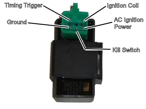
After that get youself a meter. Unplug the CDI and measure the resistance in the wiring harness (not the CDI module) between:
1) AC Ignition Power pin and Ground Pin
2) Timing Trigger Pin and Ground Pin
3) Ignition Coil Pin and Ground Pin
4) Ground Pin and your battery Negative Terminal.
When measuring resistances use the lowest resistance scale for each reading that gives a value other than open (the same reading you get when the leads are separated).
What do you read for each of those four tests?
Since your wiring has been butchered I suspect that wiring errors may be the thing that must be found and fixed. A meter is the best tool for that.