
Jackel 110R No spark
 Mar 22, 2009 | 07:43 PM
#1

Thread Starter
|
Weekend Warrior
Joined: Mar 2009
Posts: 3
Likes: 0
I have a jackel 110r that is not getting spark. I noticed the rear brake light is stuck on. The brake light worked fine until now, so it must be related to not having spark. Any ideas????
Mar 22, 2009 | 11:44 PM
#2

Electrical Expert
Likes High Voltage In The Tub!
Likes High Voltage In The Tub!
Joined: Dec 2008
Posts: 3,260
Likes: 14
From: Tracy, California, USA
The rear brake switch is adjustable, and is most likely the cause of a stuck brake light. It is not the cause of your no spark problem.
Check your kill switches first. Here is a good link with more info:
No Spark
This link is just a start. If you still have problems then report back. There are other measurements that can narrow down the problem further using a voltmeter.
Lynn Edwards
Check your kill switches first. Here is a good link with more info:
No Spark
This link is just a start. If you still have problems then report back. There are other measurements that can narrow down the problem further using a voltmeter.
Lynn Edwards
Mar 23, 2009 | 06:22 PM
#3
Thread Starter
|
Weekend Warrior
Joined: Mar 2009
Posts: 3
Likes: 0
Thanks for the update... I looked at that same site last night, I have a 4pin cdi not a 5 pin. I tried cutting the black/white wire just to see if it would do anything on the 4 pin, it did not. I just ordered a new cdi I'm hoping that will solve the problem. My son is dying to go riding, the mud season is just starting out here in New England.
Mar 23, 2009 | 10:55 PM
#4
Electrical Expert
Likes High Voltage In The Tub!
Likes High Voltage In The Tub!
Joined: Dec 2008
Posts: 3,260
Likes: 14
From: Tracy, California, USA
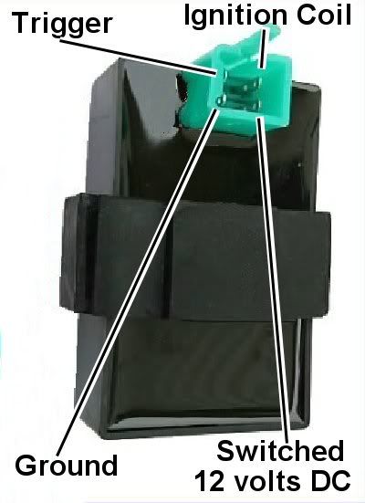
I believe the four pin CDI's are powered by 12 volts DC instead of high voltage AC off the stator. This is now a whole different story. Four pin CDI's can't have a standard kill switch since there isn't enough pins. Four pins are absolutely required for the CDI to function:
1) Ground: Everything needs a ground
2) Power: Probably 12 Volts DC in your case
3) Timing/Trigger: Tells the CDI when to fire
4) Ignition Coil: Connects to the coil primary side winding
No more pins are left for a kill switch. But the CDI can be disabled (killing spark and the engine) by other methods:
A) Disconnecting the ground or power connection to the CDI.
B) Disconnecting or shorting to ground the Timing/Trigger signal to the CDI.
So there is still a possibility that your problem is wiring related. Here is a somewhat related thread from a while ago:
Four pin CDI Thread
Go to the bottom and find the last post by AirMobile101. Look to the left of the message under his name and stats. You will see a camera icon. Click on the camera. Look for a thumbnail picture of a four pin CDI. Click on the thumbnail to get a pinout of the CDI. AirMobile101 was kind enough to put up the pinout of the 4 pin CDI.
Use an ohmmeter to verify that the CDI ground connection does indeed go to ground (remember that the ignition switch may have to be on and all kill switches disabled depending on which method is used to shut the engine down).
Using the ohmmeter make sure the ignition coil connection on the CDI goes to the coil primary. The coil primary should also measure just a few ohms to ground.
Use an ohmmeter to measure the timing trigger connection to ground at the CDI. You should read about 150 ohms or so (ignition might have to be on and all kill switches disabled, but engine not running, while measuring this).
Use a voltmeter to measure the power connection on the CDI. It should be 12 volts DC when the ignition is on.
All of the above probably sounds complicated, but it really isn't if you take it one step at a time. Let's hope it is the CDI, but if it isn't you can still find the problem and you will have a spare CDI to boot.
 May 7, 2012 | 08:32 PM
#7

Weekend Warrior
Joined: May 2012
Posts: 14
Likes: 0
i got a new cdi and a new spark plug and coil and it still wont get spark and its getting voltege to the coil but makes no spark i think it might be the regulator i dont know that much about atv's so if u can help please reply
Thanks,
sincerely, len
Thanks,
sincerely, len
Trending Topics
May 8, 2012 | 12:24 AM
#8
Electrical Expert
Likes High Voltage In The Tub!
Likes High Voltage In The Tub!
Joined: Dec 2008
Posts: 3,260
Likes: 14
From: Tracy, California, USA
1) Is this a chinese quad?
2) What size engine?
3) How many pins on your CDI?
You said you measured 'voltage to the coil'. How did you do this? Were you using a meter? Were you measuring AC or DC voltage? What scale? I'm not trying to put you on the spot - but rather trying to establish where to begin. If you're not sure just say it and we'll start at the beginning...
Voltage regulators have absolutely nothing to do with spark.
May 10, 2012 | 11:27 PM
#10
Electrical Expert
Likes High Voltage In The Tub!
Likes High Voltage In The Tub!
Joined: Dec 2008
Posts: 3,260
Likes: 14
From: Tracy, California, USA
4 pin CDI's are DC powered. Here is the generic procedure for troubleshooting "no spark" problems on a 4 pin CDI quad:
To troubleshoot no spark problems on a 4 pin DC powered CDI it makes sense
to start in the middle (the CDI), measure as much as we can and branch out from
there. For the CDI to do its thing it needs power and ground, and a trigger
pulse.
1) Unplug the CDI. Turn the ignition switch on. Set all kill switches to the
the "run" position. Use
a meter to measure the DC voltage on the pin labeled "AC ignition power" in the
wiring harness to the ground wire on the 20 volt DC scale. You should read
battery voltage (12 volts). What do you measure?
2) Leave the CDI unplugged. Use a meter to measure the resistance of the
"Ignition Trigger Pulse" pin in the wiring harness to the ground wire on the 2K
ohm scale. You should read approximately 150 ohms. What do you measure?
3) Leave the CDI unplugged. Set your meter to the lowest resistance scale you
have (like 2 ohms or 20 ohms full scale). Measure the resistance of the
"Ignition Coil" pin in the wiring harness to the ground pin. You should read
something around 0.7 ohms (but not zero ohms). What do your measure?
4) Set your meter down to the lowest scale you have for measuring AC volts. 2
volts would be ideal, but some meters don't go that low. In that case use the
lowest scale you have. While cranking the engine, measure the voltage on the
Ignition Trigger Pulse pin in the wiring harness to the ground pin. You should
measure 0.2 to 0.5 volts AC. What do you measure?
5) Now plug the CDI back in. Measure the AC voltage on the Ignition Coil pin to
the ground pin using the 200 volt scale. If you have to, use a sewing pin to
poke through the wire insulation and then put the meter probe on the sewing pin.
But don't hold your fingers on the connection during the next test - there may be
high voltage here when the engine is turning. With the ignition on and all kill
switches set to the "run" position, crank the starter motor. You should see
voltages bouncing around at random values and the meter captures all or part of a
spark event. What do you see?