
Gio 110 Hummer. Fuel tank blocked, no spark
#1
 05-29-2010, 07:55 PM


Join Date: May 2010
Location: Prince George, BC, Canada
Posts: 7
Likes: 0
Received 0 Likes
on
0 Posts
Got my son one of these Gio Hummers. All parts arrived in good condition.
Put the thing together, first problem - No Fuel from the tank. After struggling for what seemed an eternity, managed to remove the fuel tank and found that the outlet was blocked. Drilled through that and ensured all bits were out of the tank. Refitted it and put the bike back together.
Now there is no spark, OK I don't think there has ever been a spark.
Checked all connections and they "seem" to be fine. Followed the advice of another poster and disconnected the kill switch wire from the CDI. Still nothing. Continuity is fine. Battery on arrival was putting out less than 11.3V so thats on charge.
Changed the spark plug to the NGK recommended in another thread.
Once the battery is fully charged, will try again.
Can someone please tell me how to check all the kill switches? Is the wire to the CDI the only one I need to disconnect?
Thanks in Advance
#2
05-29-2010, 09:54 PM

Electrical Expert
Likes High Voltage In The Tub!
Likes High Voltage In The Tub!
Join Date: Dec 2008
Location: Tracy, California, USA
Posts: 3,260
Likes: 0
Received 13 Likes
on
13 Posts
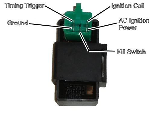
So you disconnected the kill switch wire at the CDI. That eliminates any and all kill switches as the problem since they can't kill the spark at the CDI if they aren't connected to the CDI. But just to be sure, look at the picture below to verify that you really did disconnect the right wire (and that this is the kind of CDI we are talking about):

Next disconnect the CDI and do the following:
Test 1: Set your meter to measure AC volts on the 100 or 200 volts range. Measure the AC ignition power pin to ground while cranking the engine. What do your measure? You should measure 35 to 80 volts AC. This voltage is what powers the whole ignition system.
Test 2: Set your meter to the lowest AC volts scale you have. Measure the Ignition timing trigger pin voltage to ground while cranking the engine. Waht do you measure? You should measure 0.2 to 0.5 volts AC. This signal voltage tells the CDI when to fire the spark plug.
Reconnect the CDI and measure the following:
Test 3: Dig into the back of the CDI connector and measure the Ignition Coil pin DC voltage to ground on the 200 volts scale. Crank the engine and report what you see. Do you see zero volts all the time, or zero volts and occasional random numbers? The voltage here is very narrow high voltage spikes (100 volts and up) with mostly nothing in between.
#3
05-30-2010, 01:25 PM
Join Date: May 2010
Location: Prince George, BC, Canada
Posts: 7
Likes: 0
Received 0 Likes
on
0 Posts
Thanks for the prompt reply. Reconnected the battery after charging it. Voltage at battery is 12.92V.
Tested for spark - nothing, so followed your tests and here are the results
Test 1: Set your meter to measure AC volts on the 100 or 200 volts range. Measure the AC ignition power pin to ground while cranking the engine. What do your measure? You should measure 35 to 80 volts AC. This voltage is what powers the whole ignition system.
Result of Test 1: 42.5 - 43.4 V AC
Test 2: Set your meter to the lowest AC volts scale you have. Measure the Ignition timing trigger pin voltage to ground while cranking the engine. Waht do you measure? You should measure 0.2 to 0.5 volts AC. This signal voltage tells the CDI when to fire the spark plug.
Result of Test 2: 0.2 V AC
Reconnect the CDI and measure the following:
Test 3: Dig into the back of the CDI connector and measure the Ignition Coil pin DC voltage to ground on the 200 volts scale. Crank the engine and report what you see. Do you see zero volts all the time, or zero volts and occasional random numbers? The voltage here is very narrow high voltage spikes (100 volts and up) with mostly nothing in between.
Result of Test 3: 0 Volts when cranking but shows random voltages when I release the start switch
#4
05-30-2010, 03:45 PM
Join Date: May 2010
Location: Prince George, BC, Canada
Posts: 7
Likes: 0
Received 0 Likes
on
0 Posts
OK. Found out the problem for the lack of a spark. The wires to the coil were the problem. The yellow one was pinched in the bracket, and it was unable to be grounded because the connector was on a painted area.
Now to reassemble the thing and see if it runs. Will post update once we have it running.
Now to reassemble the thing and see if it runs. Will post update once we have it running.
#5
05-30-2010, 07:49 PM
Join Date: May 2010
Location: Prince George, BC, Canada
Posts: 7
Likes: 0
Received 0 Likes
on
0 Posts
#6
08-15-2011, 06:50 PM

Hey all, I am about 2 days new to owning one of these things and already on here trying to fix it haha. I have the same problem as described, I did the three tests, the first two came in within the suggested range however I am getting 0 voltage on the third test for the ignition coil. Where do I go from here?
Thanks!
Thanks!
#7
08-15-2011, 10:50 PM
Electrical Expert
Likes High Voltage In The Tub!
Likes High Voltage In The Tub!
Join Date: Dec 2008
Location: Tracy, California, USA
Posts: 3,260
Likes: 0
Received 13 Likes
on
13 Posts
Hey all, I am about 2 days new to owning one of these things and already on here trying to fix it haha. I have the same problem as described, I did the three tests, the first two came in within the suggested range however I am getting 0 voltage on the third test for the ignition coil. Where do I go from here?
Thanks!
Thanks!
Is this a picture of your CDI?
Assuming the answer is yes, the first thing to do is eliminate all kill switches abd kill switch wiring:
Method 1) Unplug the CDI and remove the kill switch pin in the CDI connector on the wiring harness. The pin is held in with a spring tab on the pin itself. You'll have to probe into the connector and push this tab in order to extract the pin. Plug the CDI back in (kill switch wire dangling) and see if you have spark.
Method 2) Unplug the CDI. Turn on the ignition switch and set all kill switches to the run position. Use a meter to measure resistance in of the kill switch pin in the wiring harness connector to engine/frame ground. If the reistance is infinite on the 100K ohm scale then your kill switches/kill switch wiring are OK. If you measure zero ohms then you have a kill switch/wiring issue.
The other inputs your CDI needs to make spark are AC Ignition Power, and the Trigger signal. Do the following:
1) Unplug the CDI. In the wiring connector measure the resistance of the AC Ignition Power pin to the Ground pin. You should see 400 ohms or so. What do you measure?
2) Measure the resistance of the Timing/trigger pin to the ground pin. You should measure 150 ohms or so. What do you measure?
3) Leave the CDI unplugged. Set your meter to measure AC volts on the 100 volt scale. Measure the voltage on the AC Ignition Power pin to the ground pin while cranking the engine. You should see 40 to 80 volts AC while the engine is cranking. What do you measure?
4) Set your meter to measure AC volts on the lowest scale you have. Ideally this would be 2 volts but many meters don't go down this low. In that case use the lowest scale you have. Measure the voltage on the Timing Trigger pin to the Ground pin while cranking the engine. You should 0.2 t0 0.4 volts AC. What do you measure?
Now for measuring the output side of the CDI:
A) Leave the CDI unplugged. In the CDI wiring connector measure the resistance of the Ignition Coil pin to the ground pin. You should measure less than 1 ohm (but not zero ohms). What do you measure?
B) Plug the CDI back in. Set your meter to measure AC volts on the 20 volt scale. Set all kill switches to the run position. Crank the engine while measuring the voltage on the Igntition Coil pin to ground. Poke through the insulation of the wire if you can't probe the connector.
Caution: There should be moderately high voltage spikes on this wire. Make sure your fingers are not part of the circuitry. Don't touch the probe lead tips while doing this test.
What you should see is a lot of random numbers with lots of zero values as well. This is because the meter may catch all or part of the spark event voltage, with a lot of nothing in between. Describe what you see.
Note: Using a meter to measure this point produces highly variable results depending on the meter. What you really need is an oscilloscope, but most always a meter is all that is available. We have to do the best we can with what's available. Describe the meter results as accurately as you can - there is information there to chew on....
 .
.
Trending Topics
#8
08-16-2011, 03:47 PM
Quote:
Originally Posted by bigbadbob17
Hey all, I am about 2 days new to owning one of these things and already on here trying to fix it haha. I have the same problem as described, I did the three tests, the first two came in within the suggested range however I am getting 0 voltage on the third test for the ignition coil. Where do I go from here?
Thanks!
Those three tests were an abbreviated set based on the fact that kill switch issues were already eliminated. Here is the full generic test procedure for a 5 pin CDI:
Quote:
Is this a picture of your CDI?
Assuming the answer is yes, the first thing to do is eliminate all kill switches abd kill switch wiring:
Method 1) Unplug the CDI and remove the kill switch pin in the CDI connector on the wiring harness. The pin is held in with a spring tab on the pin itself. You'll have to probe into the connector and push this tab in order to extract the pin. Plug the CDI back in (kill switch wire dangling) and see if you have spark.
Method 2) Unplug the CDI. Turn on the ignition switch and set all kill switches to the run position. Use a meter to measure resistance in of the kill switch pin in the wiring harness connector to engine/frame ground. If the reistance is infinite on the 100K ohm scale then your kill switches/kill switch wiring are OK. If you measure zero ohms then you have a kill switch/wiring issue.
The other inputs your CDI needs to make spark are AC Ignition Power, and the Trigger signal. Do the following:
1) Unplug the CDI. In the wiring connector measure the resistance of the AC Ignition Power pin to the Ground pin. You should see 400 ohms or so. What do you measure?
2) Measure the resistance of the Timing/trigger pin to the ground pin. You should measure 150 ohms or so. What do you measure?
3) Leave the CDI unplugged. Set your meter to measure AC volts on the 100 volt scale. Measure the voltage on the AC Ignition Power pin to the ground pin while cranking the engine. You should see 40 to 80 volts AC while the engine is cranking. What do you measure?
4) Set your meter to measure AC volts on the lowest scale you have. Ideally this would be 2 volts but many meters don't go down this low. In that case use the lowest scale you have. Measure the voltage on the Timing Trigger pin to the Ground pin while cranking the engine. You should 0.2 t0 0.4 volts AC. What do you measure?
Now for measuring the output side of the CDI:
A) Leave the CDI unplugged. In the CDI wiring connector measure the resistance of the Ignition Coil pin to the ground pin. You should measure less than 1 ohm (but not zero ohms). What do you measure?
B) Plug the CDI back in. Set your meter to measure AC volts on the 20 volt scale. Set all kill switches to the run position. Crank the engine while measuring the voltage on the Igntition Coil pin to ground. Poke through the insulation of the wire if you can't probe the connector.
Caution: There should be moderately high voltage spikes on this wire. Make sure your fingers are not part of the circuitry. Don't touch the probe lead tips while doing this test.
What you should see is a lot of random numbers with lots of zero values as well. This is because the meter may catch all or part of the spark event voltage, with a lot of nothing in between. Describe what you see.
Note: Using a meter to measure this point produces highly variable results depending on the meter. What you really need is an oscilloscope, but most always a meter is all that is available. We have to do the best we can with what's available. Describe the meter results as accurately as you can - there is information there to chew on....
It would really help me if you were to give me the actual values that you measure as compared to saying that "they were in range". To get a spark you need a good CDI, plug, power to run the CDI (moderately high voltage AC) from the stator, a trigger signal from the stator, working kill switch connections, and all the interconnect wiring between these. That's a lot of stuff, so I'm always looking for as much information (i.e. exact measurement data) to work with as possible. Some of the above tests are complimentary in that re-enforce each other if the results are compatible, and also indicate problems if they aren't compatible. It also allows me to verify if you are doing the measurements correctly .
.
Thanks for the reply! I did all the tests and got the following results keeping in mind that my battery is low now as I have been fooling with this for a few days.....
Kill switch ruled out - infinite resistance with all switches in run position. I also removed the wire from the harness and checked, no spark.
1) 359 ohm
2) 127 ohm
3) 39 Volts
4) 0.2 Volts
A) 0.6 (on 200 OHM setting)
B) 0.0 Volts (stays at 0 and does not jump or change numbers at all on my digital multimeter) on the lowest AC Volt setting which is 200
So the only one what raises flags to myself is B, the output from the ignition coil pin to ground.
Thanks in advance!
Originally Posted by bigbadbob17
Hey all, I am about 2 days new to owning one of these things and already on here trying to fix it haha. I have the same problem as described, I did the three tests, the first two came in within the suggested range however I am getting 0 voltage on the third test for the ignition coil. Where do I go from here?
Thanks!
Those three tests were an abbreviated set based on the fact that kill switch issues were already eliminated. Here is the full generic test procedure for a 5 pin CDI:
Quote:
Is this a picture of your CDI?
Assuming the answer is yes, the first thing to do is eliminate all kill switches abd kill switch wiring:
Method 1) Unplug the CDI and remove the kill switch pin in the CDI connector on the wiring harness. The pin is held in with a spring tab on the pin itself. You'll have to probe into the connector and push this tab in order to extract the pin. Plug the CDI back in (kill switch wire dangling) and see if you have spark.
Method 2) Unplug the CDI. Turn on the ignition switch and set all kill switches to the run position. Use a meter to measure resistance in of the kill switch pin in the wiring harness connector to engine/frame ground. If the reistance is infinite on the 100K ohm scale then your kill switches/kill switch wiring are OK. If you measure zero ohms then you have a kill switch/wiring issue.
The other inputs your CDI needs to make spark are AC Ignition Power, and the Trigger signal. Do the following:
1) Unplug the CDI. In the wiring connector measure the resistance of the AC Ignition Power pin to the Ground pin. You should see 400 ohms or so. What do you measure?
2) Measure the resistance of the Timing/trigger pin to the ground pin. You should measure 150 ohms or so. What do you measure?
3) Leave the CDI unplugged. Set your meter to measure AC volts on the 100 volt scale. Measure the voltage on the AC Ignition Power pin to the ground pin while cranking the engine. You should see 40 to 80 volts AC while the engine is cranking. What do you measure?
4) Set your meter to measure AC volts on the lowest scale you have. Ideally this would be 2 volts but many meters don't go down this low. In that case use the lowest scale you have. Measure the voltage on the Timing Trigger pin to the Ground pin while cranking the engine. You should 0.2 t0 0.4 volts AC. What do you measure?
Now for measuring the output side of the CDI:
A) Leave the CDI unplugged. In the CDI wiring connector measure the resistance of the Ignition Coil pin to the ground pin. You should measure less than 1 ohm (but not zero ohms). What do you measure?
B) Plug the CDI back in. Set your meter to measure AC volts on the 20 volt scale. Set all kill switches to the run position. Crank the engine while measuring the voltage on the Igntition Coil pin to ground. Poke through the insulation of the wire if you can't probe the connector.
Caution: There should be moderately high voltage spikes on this wire. Make sure your fingers are not part of the circuitry. Don't touch the probe lead tips while doing this test.
What you should see is a lot of random numbers with lots of zero values as well. This is because the meter may catch all or part of the spark event voltage, with a lot of nothing in between. Describe what you see.
Note: Using a meter to measure this point produces highly variable results depending on the meter. What you really need is an oscilloscope, but most always a meter is all that is available. We have to do the best we can with what's available. Describe the meter results as accurately as you can - there is information there to chew on....
It would really help me if you were to give me the actual values that you measure as compared to saying that "they were in range". To get a spark you need a good CDI, plug, power to run the CDI (moderately high voltage AC) from the stator, a trigger signal from the stator, working kill switch connections, and all the interconnect wiring between these. That's a lot of stuff, so I'm always looking for as much information (i.e. exact measurement data) to work with as possible. Some of the above tests are complimentary in that re-enforce each other if the results are compatible, and also indicate problems if they aren't compatible. It also allows me to verify if you are doing the measurements correctly
.Thanks for the reply! I did all the tests and got the following results keeping in mind that my battery is low now as I have been fooling with this for a few days.....
Kill switch ruled out - infinite resistance with all switches in run position. I also removed the wire from the harness and checked, no spark.
1) 359 ohm
2) 127 ohm
3) 39 Volts
4) 0.2 Volts
A) 0.6 (on 200 OHM setting)
B) 0.0 Volts (stays at 0 and does not jump or change numbers at all on my digital multimeter) on the lowest AC Volt setting which is 200
So the only one what raises flags to myself is B, the output from the ignition coil pin to ground.
Thanks in advance!
#9
08-16-2011, 11:13 PM
Electrical Expert
Likes High Voltage In The Tub!
Likes High Voltage In The Tub!
Join Date: Dec 2008
Location: Tracy, California, USA
Posts: 3,260
Likes: 0
Received 13 Likes
on
13 Posts
...Thanks for the reply! I did all the tests and got the following results keeping in mind that my battery is low now as I have been fooling with this for a few days.....
Kill switch ruled out - infinite resistance with all switches in run position. I also removed the wire from the harness and checked, no spark.
1) 359 ohm
2) 127 ohm
3) 39 Volts
4) 0.2 Volts
A) 0.6 (on 200 OHM setting)
B) 0.0 Volts (stays at 0 and does not jump or change numbers at all on my digital multimeter) on the lowest AC Volt setting which is 200
So the only one what raises flags to myself is B, the output from the ignition coil pin to ground.
Thanks in advance!
You've got power, trigger signal, connectivety though the ignition coil. Your CDI spark isn't inhibited through the kill switch input pin. It looks like a bad CDI to me.
#10
08-17-2011, 04:57 PM