
E-ton 90 cc atv with no spark
 Nov 27, 2010 | 08:46 PM
#31

Electrical Expert
Likes High Voltage In The Tub!
Likes High Voltage In The Tub!
Joined: Dec 2008
Posts: 3,260
Likes: 14
From: Tracy, California, USA
But why are you doing this? The stator can be *completely* measured with a meter while it is still mounted on the quad. Once you take it off you can't measure it anymore. This is because some of the functional tests involve measuring AC voltages while it is spinning (i.e. driven by the starter motor). You can't do that when the quad is taken apart.
The proper procedure is to measure the resistances of the CDI pins as outlined before. Some of these tests will measure back through the Stator, and also through the ignition coil. Next some AC voltage will be measured based on what you find with the resistances.
Nov 27, 2010 | 09:14 PM
#32
Electrical Expert
Likes High Voltage In The Tub!
Likes High Voltage In The Tub!
Joined: Dec 2008
Posts: 3,260
Likes: 14
From: Tracy, California, USA

Also I think you have errors on a previous post where (I think) you were measuring resistances into the CDI module itself. I asked if it was possible that you had flipped two pins. Did you get a chance to recheck that? If you did flip those two pins it may be a good clue as to your problem.
This is the generic Chinese 5 pin CDI pinout:
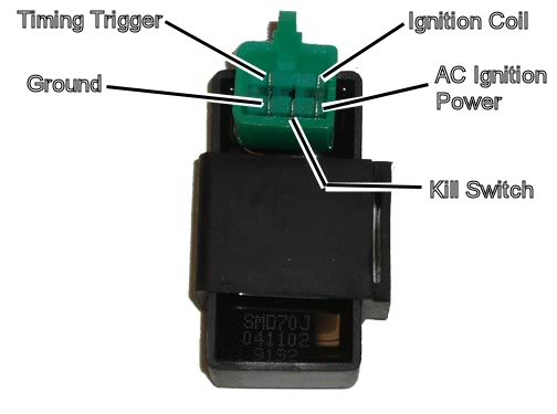
Note that I specified the pins as one looks into the CDI pins. If you are looking into the wiring harness connector note that the pins get mirror imaged because you have to unplug the connector and flip it over to look into it.
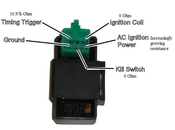
Problem 1: In your wiring harness, the timing trigger pin (Blue/White) should read roughly 140 ohms (not 350). Your AC Ignition Power pin (Black/Red) should read roughly 350 ohms (not 140). This may be just a diagram error in your picture above, or it may be that the two leads are reversed.
Problem 2: Your kill switch pin (black/white) should be open (infinite resistance), not near zero ohms. If indeed your kill switch pin is grounded then you will get no spark, and you've narrowed the problem down. Did you make sure your ignition switch was on, and that all your kill switches were in the "run" position before measuring this pin? [Important note to anyone reading this: This is an eton thread, but right now we are talking about a generic chinese quad. Etons are different. Do not infer anything in this paragraph over to eton quads.]
Problem 3: Your ground wire (green) reads 0.6 ohms to ground, while your ignition coil output wire (black/yellow) reads 0.2 ohms to ground. This is unlikely. The ignition coil output wire goes to ground through the ignition coil primary winding, which has a low resistance of less than an ohm, but it is not zero (and certainly not negative). Therefore the resistance to ground through the coil should be more than the resistance to ground directly through the ground wire. It is remotely possible that you have a bad connection on the ground wire to the CDI. Is it possible you got the Ground/Coil wires flipped as well?
Nov 27, 2010 | 10:53 PM
#33

Thread Starter
|
Trailblazer
Joined: Sep 2010
Posts: 35
Likes: 0
Lynn, I was not going to pull the flywheel, I just wanted to know where the stator was. My wire diagram did not show one and the cdi had 6 wires like you stated. I might need to buy another meter, The readings I got on my meter was 1 . on all 5 wires. Also, my cdi dont have a plug for all the wires like you are talking about which was confusing me. Two of the five wires are in one plug, the other 3 wires are plugged in separately.
Nov 27, 2010 | 11:40 PM
#34
Electrical Expert
Likes High Voltage In The Tub!
Likes High Voltage In The Tub!
Joined: Dec 2008
Posts: 3,260
Likes: 14
From: Tracy, California, USA
Lynn, I was not going to pull the flywheel, I just wanted to know where the stator was. My wire diagram did not show one and the cdi had 6 wires like you stated. I might need to buy another meter, The readings I got on my meter was 1 . on all 5 wires. Also, my cdi dont have a plug for all the wires like you are talking about which was confusing me. Two of the five wires are in one plug, the other 3 wires are plugged in separately.
If your scale is set too low you may have to raise it up. For example, if you are trying to measure something which has 400 ohms of resistance, and your meter is set to 200 ohms full scale, then your meter will read infinite. This is because 400 ohms is above the 200 ohm maximum that your meter is set to measure. If you were to raise the meter to 500 ohm full scale then you would read 400 ohms. If you were to set your meter to 2K ohms full scale (same as 2000 ohms) you would read 0.40K ohms (same as 400 ohms). I don't know what scale values you have on your meter (it varies from meter to meter), but choosing the lowest scale that gives you a reading other than infinite is the best scale to use.
If you set the meter resistance scale way high you should be able to measure the resistance of your skin (20.0K to 200K ohms [same as 20,000 ohms to 200,000 ohms]) from hand to hand. The resistance of your tongue will be far lower. This is just another way to see if your meter is working right.
Sorry for the confusion on the CDI plug (or lack thereof). I'm more used to connectors than the pigtail leads. Whether the wires are in a plastic connector housing or not just measure each wire's resistance to ground.
As we go forward we will have to use the wiring diagram as a guideline and not gospel. We already know that it doesn't match your quad.
Nov 28, 2010 | 12:26 AM
#35

Trailblazer
Joined: Mar 2010
Posts: 93
Likes: 0
From: Kailua-Kona, HI
is it possible your meter has different plug ins for different uses? some meters have 3 plug ins for those alligator clips or needle/prongs to check for voltage and ohms for example you use two different plug ins on the meter. if you use the voltage plug in, your meter will not read anything as you are not in the ohm socket of the meter... my meter has this. I'm not sure if yours does or not.
as stated short the prongs together to see if your meter is registering anything. also turn off any peak hold if it's on and keeping the readout at 1.
as stated short the prongs together to see if your meter is registering anything. also turn off any peak hold if it's on and keeping the readout at 1.
Nov 28, 2010 | 07:56 AM
#36

Trailblazer
Joined: Nov 2010
Posts: 33
Likes: 0
From: Greer, SC

Also I think you have errors on a previous post where (I think) you were measuring resistances into the CDI module itself. I asked if it was possible that you had flipped two pins. Did you get a chance to recheck that? If you did flip those two pins it may be a good clue as to your problem.
Problem 2: Your kill switch pin (black/white) should be open (infinite resistance), not near zero ohms. If indeed your kill switch pin is grounded then you will get no spark, and you've narrowed the problem down. Did you make sure your ignition switch was on, and that all your kill switches were in the "run" position before measuring this pin? [Important note to anyone reading this: This is an eton thread, but right now we are talking about a generic chinese quad. Etons are different. Do not infer anything in this paragraph over to eton quads.]
Nov 28, 2010 | 12:25 PM
#37
Electrical Expert
Likes High Voltage In The Tub!
Likes High Voltage In The Tub!
Joined: Dec 2008
Posts: 3,260
Likes: 14
From: Tracy, California, USA
All the reading now make sense except the kill switch wire. At zero ohms you will not get spark...
Yes, your kill switch is grounded. Most quads have multiple kill switches, and anyone of them can ground this pin. The four typical kill switches on a generic chinese quad are:
1) One section of the two section ignition switch. This is what shuts your quad down when you turn off the ignition switch.
2) The handle bar kill switch. Sometimes you need to place the switch in the center position and push it in till it goes "click" to enable spark.
3) The Tether pull switch. This switch is held open with a rubber plug. When you pull the plug off the switch contacts close, killing the spark.
4) The remote control module. The remote must have the ability to shut down the quad too.
All of these can be eliminated by unplugging them. Monitor the resistance of the kill switch wire at the CDI connector. Unplug each of the switches one by one until the short goes away. If the short remains look for a pinched wire in the harness.
I'm still wondering if you have the values for the AC Ignition Power and the Ignition Coil pins backwards. In any case the values aren't right and therefore I believe the CDI is bad.
Here is a internal schematic of the CDI pictured above:
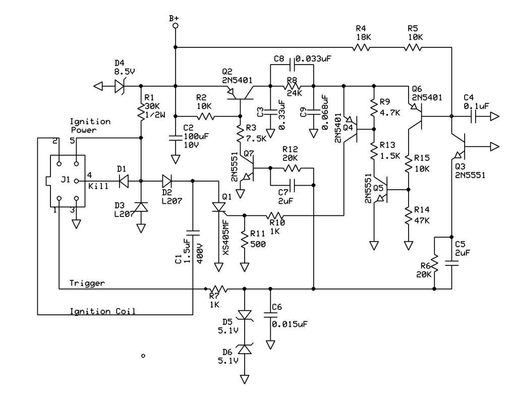
If the AC Ignition Power and Ignition Coil pins were reversed I would guess that D1, D2, and Q1 are shorted. That would happen if the AC Ignition Power pin got inadvertently hooked up to battery voltage.

1) One section of the two section ignition switch. This is what shuts your quad down when you turn off the ignition switch.
2) The handle bar kill switch. Sometimes you need to place the switch in the center position and push it in till it goes "click" to enable spark.
3) The Tether pull switch. This switch is held open with a rubber plug. When you pull the plug off the switch contacts close, killing the spark.
4) The remote control module. The remote must have the ability to shut down the quad too.
All of these can be eliminated by unplugging them. Monitor the resistance of the kill switch wire at the CDI connector. Unplug each of the switches one by one until the short goes away. If the short remains look for a pinched wire in the harness.
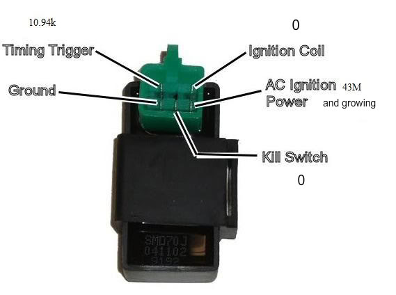
...I rechecked my resistances and put them into your drawing so we'd both be on the same page. I guess my translation from garage to computer wasn't working so well. LOL. The pin I marked as increasing resistance started at 600k Ohm and I let it grow steadily to 15M Ohm before stopping.

....
....
Here is a internal schematic of the CDI pictured above:
If the AC Ignition Power and Ignition Coil pins were reversed I would guess that D1, D2, and Q1 are shorted. That would happen if the AC Ignition Power pin got inadvertently hooked up to battery voltage.
Nov 28, 2010 | 03:20 PM
#38
Trailblazer
Joined: Nov 2010
Posts: 33
Likes: 0
From: Greer, SC
I don't know of a remote on this quad nor does PeaceSports mention one on their website so I don't believe that's it. The tether kill switch I've already taken out of the equation as it was questionable at best in it's present condition and I'm not going to be chasing my kids around while their riding anyway. I checked out my key switch and was definately getting continuity between ground and the black/white wire so I've fixed that now hopefully. Checking the resistances on my son's CDI from his 110 here are the readings. So I figure the one on my 70 is good since the readings match. Just now I got the brilliant idea to swap her CDI over to his atv and it started right up, so I'm going to have to try that will all the parts. The only thing that won't swap over is the key switch as hers is a 5 pin and his is a 4 pin. Why I didn't think of this before I don't know, guess I'm kinda slow these days. LOL.
Dec 29, 2010 | 03:00 PM
#39
Thread Starter
|
Trailblazer
Joined: Sep 2010
Posts: 35
Likes: 0

On your meter short the two leads together while measuring resistance. You should see zero ohms. Then when you disconnect the leads the meter should go to infinite (often a "1" in the left most digit of the meter. This allows you to check your meter operation independantly of your quad.
If your scale is set too low you may have to raise it up. For example, if you are trying to measure something which has 400 ohms of resistance, and your meter is set to 200 ohms full scale, then your meter will read infinite. This is because 400 ohms is above the 200 ohm maximum that your meter is set to measure. If you were to raise the meter to 500 ohm full scale then you would read 400 ohms. If you were to set your meter to 2K ohms full scale (same as 2000 ohms) you would read 0.40K ohms (same as 400 ohms). I don't know what scale values you have on your meter (it varies from meter to meter), but choosing the lowest scale that gives you a reading other than infinite is the best scale to use.
If you set the meter resistance scale way high you should be able to measure the resistance of your skin (20.0K to 200K ohms [same as 20,000 ohms to 200,000 ohms]) from hand to hand. The resistance of your tongue will be far lower. This is just another way to see if your meter is working right.
Sorry for the confusion on the CDI plug (or lack thereof). I'm more used to connectors than the pigtail leads. Whether the wires are in a plastic connector housing or not just measure each wire's resistance to ground.
As we go forward we will have to use the wiring diagram as a guideline and not gospel. We already know that it doesn't match your quad.
 Jan 1, 2011 | 12:39 AM
#40
Electrical Expert
Likes High Voltage In The Tub!
Likes High Voltage In The Tub!
Joined: Dec 2008
Posts: 3,260
Likes: 14
From: Tracy, California, USA

In a previous post you said you had these wires coming out of your CDI:
1) Blue on White
2) Red on White
3) Red on Black
4) White on Black
5) Black
But in your last post you described a resistance on a White on Blue wire. Is the White on Blue really a Red on White? Vice Versa?
All the other colors match. So for those wires based on your readings I would say that:
1) Blue on White: Ignition coil wire
2) Mystery Color?: Timing Trigger
3) Red on Black: AC Ignition Power
4) White on Black: Kill Switch
5) Black: Ground
Find out what the color scheme is for wire #2 and report back.
Set you meter to measure AC volts on the 200 volt scale. Test your meter by plugging the meter probes into one of your household power outlets. You should read 120 volts AC.
Leave the CDI disconnected. Turn on the ignition and set all your kill switches to the "run" position. While cranking the starter motor measure the AC voltage on the AC Ignition Power pin (Red on Black) to the Ground Pin (black). What voltage do you measure?
Plug the CDI back in. Measure the AC voltage on the Ignition Coil Pin (Blue on White) to the Ground pin (black) while cranking the starter. If you have trouble getting at the wires with the CDI plugged in then use a good solid frame ground instead of the black wire, and push your probe through the insulation on the Ignition Coil wire. What voltage do you measure?