
E-ton sierra
 Jul 3, 2011 | 01:37 PM
#1

Thread Starter
|
Weekend Warrior
Joined: Jul 2011
Posts: 3
Likes: 0
I'm currently working on an e-ton sierra 4 wheeler.I have no spark already replaced the CDI module which is a 5 wire CDI. Need to find out values so I can test the stator and power to the CDI module.
Jul 6, 2011 | 03:20 PM
#2

Electrical Expert
Likes High Voltage In The Tub!
Likes High Voltage In The Tub!
Joined: Dec 2008
Posts: 3,260
Likes: 14
From: Tracy, California, USA
It looks like my sierra wiring diagram doesn't match since it has a 6 wire CDI. But we should be able to figure it out anyway with some more info.
1) On your CDI connector(s), what are the wire colors of the 5 wires? Note: Report only the wire colors in the main wiring harness if they are different from the short pigtail wires on the CDI module itself.
2) On your stator (wires coming out of the engine side cover), how many wires are there, and what are the wire colors? Again, report only the wire colors in the main harness - not the wire colors of the short wires coming out of the engine.
3) Do you have a remote start/stop module installed?
4) What are the wire colors on your ignition coil?
Jul 6, 2011 | 09:46 PM
#3
Thread Starter
|
Weekend Warrior
Joined: Jul 2011
Posts: 3
Likes: 0
Here are the answers to the questions you asked.
Wire colors on CDI module
white/blue stripe ,black,blue/yellow stripe, blue/white stripe, black/red stripe.
wire colors and how many at the stator 5 wires
white,black, yellow/orange stripe, white/orange stripe, black/red stripe
Do you have a remote start/stop module installed? No
What are the wire colors on your ign. coil? 1 wire and it is white/blue stripe
I forgot to mention that when I first got this machine had excellent spark,But would not start so I cleaned the carb. and fuel tank out.Would start and run but only for a few seconds.Then it quit starting thats when I checked and found no spark.Replaced CDI module per mechanic I spoke with at an E-ton dealer still no spark.
Jul 7, 2011 | 03:26 PM
#4
Electrical Expert
Likes High Voltage In The Tub!
Likes High Voltage In The Tub!
Joined: Dec 2008
Posts: 3,260
Likes: 14
From: Tracy, California, USA
Unplug the CDI wires and do the following tests with a meter:
1) Measure resistance in the wiring harness between the Blk/Red wire and the black wire using the 2K ohm scale. I think this will be the AC ignition power wire (Blk/red, black is ground), and it should read roughly 400-500 ohms. What do you measure?
2) Measure the resistance of the Blu/Yel wire to the black (ground) wire using the 2K ohm scale. I think this will be the ignition trigger wire and should read 100-200 ohms. What do you measure?
3) Set all your kill switches to the "run" position [lanyard tether plug installed (if you have one), ignition switch on, and left handlebar kill switch in run mode]. Measure the resistance of the Blu/Wht wire to the black (ground) wire. I think this will be the kill switch input to the CDI. This should be a short (zero ohms). What do you measure?
4) Measure the resistance of the Wht/Blu wire to ground. Use a low scale like 200 ohms. I think this will be the ignition coil primary connection, and will read less than 1 ohm (but not zero ohms). What do you measure?
These tests accomplish two things: They confirm (or blow apart) my theory about how your quad is wired up, and they make a start on verifying some of the connections necessary for the ignition system to work.
4) Measure the Wht/Blu wire to the black (ground) wire
Jul 13, 2011 | 06:59 PM
#5
Thread Starter
|
Weekend Warrior
Joined: Jul 2011
Posts: 3
Likes: 0
1) measure between blk./red,blk.is ground. open
2)blu./yel wire to black. 111 ohms
3) blu/wht. wire to black ground wire. 4.6 ohms
4) wht./blu wire to ground. .6 ohms
5)wht./blu. wire to the black ground wire. .6 ohms
2)blu./yel wire to black. 111 ohms
3) blu/wht. wire to black ground wire. 4.6 ohms
4) wht./blu wire to ground. .6 ohms
5)wht./blu. wire to the black ground wire. .6 ohms
Jul 15, 2011 | 10:59 PM
#6
Electrical Expert
Likes High Voltage In The Tub!
Likes High Voltage In The Tub!
Joined: Dec 2008
Posts: 3,260
Likes: 14
From: Tracy, California, USA
I was too zonkered after work on Wednesday to post anything, and when I went though all the posts yesterday I missed this one. Sorry  .
.
My comments are embedded within your results below:
.My comments are embedded within your results below:
1) measure between blk./red,blk.is ground. open [This is not right. This is probably the cause of your problem. Down near the stator wires where they come out of the engine cover, find the Blk/red wire in the wiring harness that connects with the stator wires. Disconnect the stator wire that connects with the Blk/red wire in the wiring harness. Measure the resistance looking into that stator wire to engine ground. Is it still open? What do you measure? If it is still measuring open looking into the stator then the problem is a bad stator. If it measures 400 ohms or so then there is a wiring problem between the CDI (one end of a single blk/red wire) and the stator connection (the other end of the blk/red wire)].
2)blu./yel wire to black. 111 ohms [OK]
3) blu/wht. wire to black ground wire. 4.6 ohms [This reads a little high, but I think it will still work. We'll come back to this if things still don't work after looking into more obvious problems].
4) wht./blu wire to ground. .6 ohms [OK]
5)wht./blu. wire to the black ground wire. .6 ohms [This is the same test as #4 {A typo in my original list of questions...}]
Oct 2, 2011 | 08:35 PM
#7

Weekend Warrior
Joined: Oct 2011
Posts: 3
Likes: 0
From: Las Cruces
Hi,
Newbie here, and I dont mean to hijack the thread, but I have the exact same problem!
Here are my readings:
1: 777 ohm
2: 522 ohm
3: .7 ohm
4: .5 ohm
Do these seem too far out of range?
Thanks,
Tracy
Newbie here, and I dont mean to hijack the thread, but I have the exact same problem!
Here are my readings:
1: 777 ohm
2: 522 ohm
3: .7 ohm
4: .5 ohm
Do these seem too far out of range?
Thanks,
Tracy
Trending Topics
Oct 7, 2011 | 12:27 AM
#8
Electrical Expert
Likes High Voltage In The Tub!
Likes High Voltage In The Tub!
Joined: Dec 2008
Posts: 3,260
Likes: 14
From: Tracy, California, USA
What kind of eton? Is this a sierra 90 too?
A) Unplug the CDI. Measure the AC voltage on the black/red wire on the CDI connector to ground while cranking the engine. What voltage do you measure? This will be something in the neighborhood of 50-80 volts AC.
B) Measure the AC voltage on the blue yellow wire to ground while cranking the engine (ignition on and all kill switches in the run position). This will be a really low value like 0.2 to 0.4 volts, so use the lowest AC meter scale you have. It should not read zero volts. What do you measure?
C) Plug the CDI back in. Measure the AC voltage on the White/Blue wire voltage while cranking the engine on the 20 volt scale (again, ignition on and all kill switches in the run position). If you can't get at the pin at the CDI connector then probe in with a sharp pin through the wire insulation. Just make sure your fingers are not part of the circuit. Even though the average voltages are low the peak voltages here are quite high. You should see random numbers with a lot of zeros interspersed. This also depends on your meter design. Different meters read differently since we are attempting to measure something that meters are not designed to do. Describe what you see here in detail...
The resistance values you posted are different then the chinese quads I'm used to, but they aren't so different that they are red flags. I don't have eton specs so I'm fishing for additional info. Even if I did have the eton specs and the resistances were within range we would still need to do the voltage tests.
Last edited by LynnEdwards; Oct 7, 2011 at 12:29 AM. Reason: add more info...
Oct 8, 2011 | 01:51 PM
#9
Weekend Warrior
Joined: Oct 2011
Posts: 3
Likes: 0
From: Las Cruces
Lynn,
Thanks for helping...
Yes, its a 2001 E-TON DXL90G, just like original poster. It has maybe 50 hours on it, it was purchased new by my in laws, who eventually gave it to me.
In the measurements below, I used both a Fluke 16 non-RMS DMM and a TEK oscilloscope.
Black/Red power wire: w/o CDI = 93 VAC, w/ CDI = 47 VAC (no scope measurements, voltage too high w/o a divider probe)
Blue/Yel trigger wire: w/o CDI = .47 VAC, W/CDI = .43 VAC, scope shows a 7 volt negative pulse followed by a 7v positive pulse, each about 2ms in width. The neg to pos peak are about 14 mS apart, while the pairs are separated by 83.4mS.
the white/blue going to the coil: w/coil=.06VAC, w/o coil=.60VAC. Scope shows a 3.2v positive going pulse, about 2mS in duration, with the pulses about 21.4mS apart. Once in a while, especially after letting it sit between trys, the pulse will be 10v peak, but then quickly settles to about 3v peak.
My owners manual also has the wrong wiring diagram: it shows 6 wires into the CDI while there are only 5. Sounds like we now know what they do!
Many thanks,
Tracy
Oct 8, 2011 | 10:30 PM
#10
Electrical Expert
Likes High Voltage In The Tub!
Likes High Voltage In The Tub!
Joined: Dec 2008
Posts: 3,260
Likes: 14
From: Tracy, California, USA
My comments in blue...
Lynn,
Thanks for helping...
Yes, its a 2001 E-TON DXL90G, just like original poster. It has maybe 50 hours on it, it was purchased new by my in laws, who eventually gave it to me.
In the measurements below, I used both a Fluke 16 non-RMS DMM and a TEK oscilloscope. [Wow, you are well equipped ]
]
Black/Red power wire: w/o CDI = 93 VAC, w/ CDI = 47 VAC (no scope measurements, voltage too high w/o a divider probe) [This looks fine]
Blue/Yel trigger wire: w/o CDI = .47 VAC, W/CDI = .43 VAC, scope shows a 7 volt negative pulse followed by a 7v positive pulse, each about 2ms in width. The neg to pos peak are about 14 mS apart, while the pairs are separated by 83.4mS. [Here's what I get on my quad (the embedded picture won't be blue):
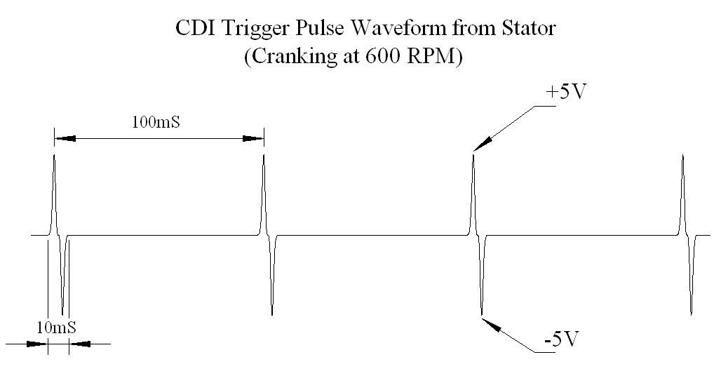
This is a little different than yours, but I don't have an eton. Note that my pulse pair is inverted from yours. The 7 volts versus 5 volts is OK. Also the 14 mS versus the 10 mS just means our stator designs are a little differrent. The 84mS time between pairs just means your starter cranks a bit faster than mine]
the white/blue going to the coil: w/coil=.06VAC, w/o coil=.60VAC. Scope shows a 3.2v positive going pulse, about 2mS in duration, with the pulses about 21.4mS apart. Once in a while, especially after letting it sit between trys, the pulse will be 10v peak, but then quickly settles to about 3v peak. [Hmmm... This seems all wrong. The fact that there is any activity at all suggest that the CDI is {sort of} being fired, but the output is all wrong. This suggests a bad CDI. This is what I would expect to see on my chinese quad at the ignition coil primary:
 ]
]
My owners manual also has the wrong wiring diagram: it shows 6 wires into the CDI while there are only 5. Sounds like we now know what they do!
Many thanks,
Tracy
Thanks for helping...
Yes, its a 2001 E-TON DXL90G, just like original poster. It has maybe 50 hours on it, it was purchased new by my in laws, who eventually gave it to me.
In the measurements below, I used both a Fluke 16 non-RMS DMM and a TEK oscilloscope. [Wow, you are well equipped
]Black/Red power wire: w/o CDI = 93 VAC, w/ CDI = 47 VAC (no scope measurements, voltage too high w/o a divider probe) [This looks fine]
Blue/Yel trigger wire: w/o CDI = .47 VAC, W/CDI = .43 VAC, scope shows a 7 volt negative pulse followed by a 7v positive pulse, each about 2ms in width. The neg to pos peak are about 14 mS apart, while the pairs are separated by 83.4mS. [Here's what I get on my quad (the embedded picture won't be blue):
This is a little different than yours, but I don't have an eton. Note that my pulse pair is inverted from yours. The 7 volts versus 5 volts is OK. Also the 14 mS versus the 10 mS just means our stator designs are a little differrent. The 84mS time between pairs just means your starter cranks a bit faster than mine]
the white/blue going to the coil: w/coil=.06VAC, w/o coil=.60VAC. Scope shows a 3.2v positive going pulse, about 2mS in duration, with the pulses about 21.4mS apart. Once in a while, especially after letting it sit between trys, the pulse will be 10v peak, but then quickly settles to about 3v peak. [Hmmm... This seems all wrong. The fact that there is any activity at all suggest that the CDI is {sort of} being fired, but the output is all wrong. This suggests a bad CDI. This is what I would expect to see on my chinese quad at the ignition coil primary:
]My owners manual also has the wrong wiring diagram: it shows 6 wires into the CDI while there are only 5. Sounds like we now know what they do!
Many thanks,
Tracy