Regulator Out Put Voltage / Connection ??
#11
 04-11-2010, 08:03 PM


Any info would be good. Also what is your cdi box look like as far as the plugs. I have been lookin on ebay for one that is listed for my engine but haven't found one yet. Also emailed some sellers to see if their cdi worked with my model number but haven't got and good responses. My owners manual showes 2 plugs. One 4 pin plug and one 2 pin plug. All 4 wires are used on the 4 pin and 1 wire used on the 2 pin plug. A lot like the setup shown in the wiring diagram above in this forum. I have seen cdi boxes on ebay with this plug layout. But some have real square plugs and another style of cdi has more rounded edges to the plugs. Both cdi's have a 4 pin/2 pin plug combo. So far I have tried 2 of the real square style plugs. The first one smoked and the secone did nothing. Remember I actually don't have the part of the wiring harness that plugs into the cdi. I am wiring the cdi from scratch.
#12
04-11-2010, 09:49 PM

Electrical Expert
Likes High Voltage In The Tub!
Likes High Voltage In The Tub!
Join Date: Dec 2008
Location: Tracy, California, USA
Posts: 3,260
Likes: 0
Received 12 Likes
on
12 Posts
...Tested again the 3 yellow wires direct from the stator and as before each combination provided 19 volts. I then increased to approx double the revs and the readings all increased to 39 volts , again regardless of combination.
From this i am guessing that the staor is working fine and that the prob lies with the reg/rect, either wrong item or from a faulty batch ???...
From this i am guessing that the staor is working fine and that the prob lies with the reg/rect, either wrong item or from a faulty batch ???...
#13
04-11-2010, 10:12 PM
Electrical Expert
Likes High Voltage In The Tub!
Likes High Voltage In The Tub!
Join Date: Dec 2008
Location: Tracy, California, USA
Posts: 3,260
Likes: 0
Received 12 Likes
on
12 Posts
Any info would be good. Also what is your cdi box look like as far as the plugs. I have been lookin on ebay for one that is listed for my engine but haven't found one yet. Also emailed some sellers to see if their cdi worked with my model number but haven't got and good responses. My owners manual showes 2 plugs. One 4 pin plug and one 2 pin plug. All 4 wires are used on the 4 pin and 1 wire used on the 2 pin plug. A lot like the setup shown in the wiring diagram above in this forum. I have seen cdi boxes on ebay with this plug layout. But some have real square plugs and another style of cdi has more rounded edges to the plugs. Both cdi's have a 4 pin/2 pin plug combo. So far I have tried 2 of the real square style plugs. The first one smoked and the secone did nothing. Remember I actually don't have the part of the wiring harness that plugs into the cdi. I am wiring the cdi from scratch.
Use the following picture to answer the next few questions:
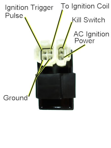
These 2 connector (4 pin and 2 pin) CDI's come in two flavors:
One is powered directly off a moderately high voltage AC line (80 to 300 volts AC) coming off the stator. Look at the wire color on the AC Ignition Power pin in the wiring harness. What is it? Look at the wire bundle coming out of the stator (this comes out of the engine). Follow the wire bundle to where it plugs into the main wiring harness. On the main wiring harness at the stator connector (or connectors), do you see the same color wire? Usually this is black/red. If you see this wire then your CDI is AC powered. AC powered CDI's are much more common than DC powered CDI's.
The other flavor of CDI is powered off +12 volts DC. The 12 volt DC power is wired into the CDI at the same pin as for the AC powered CDI shown above. Inside the CDI there is a voltage convertor that takes 12 volts DC and makes the moderately high voltage necessary to make the CDI work. As a result, the DC powered CDI's are often slightly bigger than their AC powered counterpart. But other wise they look identical. For a DC powered CDI there will *not* be a wire in the harness at the stator connector(s) that match the wire color at the CDI AC ignition power pin. Another piece of info: It is very common for AC powered CDI's to smoke (and sometimes throw shrapnel) when wired into a DC powered wiring harness.
On your CDI connector, what are the wire colors on each pin of the CDi shown above?
I've asked a lot of questions. Please try to answer them all as best you can. I'm fishing for as much information as possible since there are a lot of unknowns here.
#14
04-12-2010, 08:17 AM
Since I didn't have a plug to plug into the cdi box I used small insulated solderless connectors that fit each pin on the cdi box and ran wire to each destination. I have my current cdi box wired as shown in your last reply except for the kill switch pin. I don't have anything hooked to that pin. Does it need to be hooked up to work? Does that wire go through the kill swich and then to ground? If I still can't get it to work then I would say I got an ac type box. I know for sure I need a dc box. I have been shopping ebay for a cdi box and a lot of sellers don't seem to know if there boxes are dc. My old engine used an ac type cdi box. So next I will need a voltage regulator to work with this new engine. I was trying to tackle the spark problem first before I got involved in the regulator. I have the 3 yellow wires from my stator.
#15
04-12-2010, 08:24 AM
Also do you know if the spark plug coil is the same for ac and dc type systems. My old engine system was ac type and my new engine is dc but I am trying to reuse the same spark plug coil. In the diagram of the cdi above, the one pin is labled ac power. Since my cdi system is dc this is were I am applying the +12V dc.
#16
04-12-2010, 10:28 PM
Electrical Expert
Likes High Voltage In The Tub!
Likes High Voltage In The Tub!
Join Date: Dec 2008
Location: Tracy, California, USA
Posts: 3,260
Likes: 0
Received 12 Likes
on
12 Posts
...If I still can't get it to work then I would say I got an ac type box. I know for sure I need a dc box. I have been shopping ebay for a cdi box and a lot of sellers don't seem to know if there boxes are dc. My old engine used an ac type cdi box. So next I will need a voltage regulator to work with this new engine. I was trying to tackle the spark problem first before I got involved in the regulator. I have the 3 yellow wires from my stator.
#17
04-12-2010, 10:48 PM
Electrical Expert
Likes High Voltage In The Tub!
Likes High Voltage In The Tub!
Join Date: Dec 2008
Location: Tracy, California, USA
Posts: 3,260
Likes: 0
Received 12 Likes
on
12 Posts
Yes again. On a DC powered CDI the +12 volts (power) goes to the same powere pin as an AC powered CDI.
#18
04-13-2010, 07:24 AM
Thanks to Lynn and dirtboyuk for the help. I have found a cdi box that looks like it possibly would be a dc type. It is a kuzuma brand cdi and dirtboyuk stated he had the same engine and found his through a kuzuma source. Also it is larger in size than the other cdi's I have been trying and LynnEdwards had some info that said dc cdi's tend to be a little larger size because they convert to ac internally. I will know in a few days when I get the cdi if it works. I will post my results. If it doesn't work then I will look into the hammerhead direction as suggested. Thanks again.
#19
04-15-2010, 04:41 PM
#20
04-15-2010, 11:02 PM
Electrical Expert
Likes High Voltage In The Tub!
Likes High Voltage In The Tub!
Join Date: Dec 2008
Location: Tracy, California, USA
Posts: 3,260
Likes: 0
Received 12 Likes
on
12 Posts
Here's another test to accomplish the same thing. Lets see if the data matches...
1) Turn on the ignition switch. Disconnect the CDI (this step is important). Measure the "AC Ignition Power" pin on the CDI wiring harness pin to ground. Do you measure 12 volts DC? If so you need a DC powered CDI.
2) Switch to AC volts on your voltmeter on the 100 volt (or so) AC scale. Turn on the ignition and crank the starter. While cranking measure the AC voltage on the same pin on the CDI wiring harness (the CDI is still disconnected). What do you measure? If you measure 50-80 volts AC then you have an AC powered CDI.
Reconnect the appropriate CDI for the following tests (DC or AC).
To get spark you need a working spark plug, ignition coil, CDI, Stator, and correct wiring. Lets start isolating the problem. The first step (done above) was to see if your CDI is being powered at all, and what kind of CDI you need.
After that we need to see if your CDI is getting a trigger pulse from the CDI. Measure the Ignition Timing Trigger Pulse voltage to ground at the CDI while cranking the engine. It should be about 0.4 volts AC at cranking speeds. What do you measure?
Set you meter to both DC and AC scales and measure the ignition coil primary pin on the CDI while cranking the engine. Make sure the kill switches are off or the kill switch pin to the CDI is disconnected. It should be a bunch of random numbers. What do you see? What is the peak value?

