TAO TAO 110 cc electrical issues?
#11
 05-27-2011, 11:47 PM


Electrical Expert
Likes High Voltage In The Tub!
Likes High Voltage In The Tub!
Join Date: Dec 2008
Location: Tracy, California, USA
Posts: 3,260
Likes: 0
Received 12 Likes
on
12 Posts
The rectifier you linked to will not work like you think it will. The 110cc quad stator already has one side of the single stator battery charge coil grounded. A full bridge rectifier needs both AC input leads floating from ground. The ground connection is on the other side of the bridge rectifier diodes for the device you gave in the example. You could use two diodes out of four in the bridge to form a full wave rectifier and then regulate it to 13.5 to 14.5 volts using another regulator. This is a lot of work, but I like to tinker and suspect you do too.
My 150cc quad has a single phase 8 pole stator (seven of the eight poles are for battery charging). It can put out 55 watts (about 4.5 amps at 12 volts at high engine speed). It uses a bridge recitifer on the regulator/rectifier input (in other words neither end of the stator battery charge windings are grounded). Your 110cc machine with a single coil will put out much less current (but I've never actually measured one). So I think a 35 amp rectifier is way overkill. You won't need to worry about a heat sink...
Three phase charging systems use a modified version of the bridge rectifier using six diodes instead of four for the rectifier part of the rectifier/regulator. The three phase windings are floating with respect to ground - they get grounded on the other side of the rectifier diodes just like the single phase bridge rectifier system on my 150cc quad,
how many amps would this Tao Tao rectifier be?
I think I am going to go and build my own regulator and rectifier like i did with my bike for my boys quad. that system works good...at least on my bike.
single phase rectifier
theres just no heatsink on that rectifer. so I can go ahead and use the old bunk reg rec. just take the guts out and use the heatsink. i figure 35 amp should be good.
regulator
I have this similar setup on my chopper. works good. at least i have never had a problem...yet. the regulator is the same. the rectifier is this one
the cb 750 has a 3 phase charging system. I havent taken the bunk reg rec off the quad yet to see if theres enough wires and what the wires are and all that jazz.
I think I am going to go and build my own regulator and rectifier like i did with my bike for my boys quad. that system works good...at least on my bike.
single phase rectifier
theres just no heatsink on that rectifer. so I can go ahead and use the old bunk reg rec. just take the guts out and use the heatsink. i figure 35 amp should be good.
regulator
I have this similar setup on my chopper. works good. at least i have never had a problem...yet.
the regulator is the same. the rectifier is this one the cb 750 has a 3 phase charging system. I havent taken the bunk reg rec off the quad yet to see if theres enough wires and what the wires are and all that jazz.
#12
05-28-2011, 10:31 AM

Join Date: May 2010
Location: southwest Pa
Posts: 16
Likes: 0
Received 0 Likes
on
0 Posts
how about this one
honda parts are always better. hondas are the best actually in my book. figure ill have to cut the connector off and solder or make my own connections which is not a problem. so im guessing by the wires all would correspond except theres a black wire on the quad and a green wire on the new honda reg rec. so black to green? the way id see it. should work perfect then. and thats not much money for good honda parts i guess. and not much time.
on a separate issue i got more work to do to this thing. the front control arms are all loose and the chain has so much slack in it its hitting the swingarm.
#13
05-28-2011, 10:09 PM
Electrical Expert
Likes High Voltage In The Tub!
Likes High Voltage In The Tub!
Join Date: Dec 2008
Location: Tracy, California, USA
Posts: 3,260
Likes: 0
Received 12 Likes
on
12 Posts
how about this one
honda parts are always better. hondas are the best actually in my book. figure ill have to cut the connector off and solder or make my own connections which is not a problem. so im guessing by the wires all would correspond except theres a black wire on the quad and a green wire on the new honda reg rec. so black to green? the way id see it. should work perfect then. and thats not much money for good honda parts i guess. and not much time....
In your eBay lisiting link I see nothing stating that this is a "Honda" part. Sure they are "authorized OEM retailers" of a "manufacturer", and their parts "fit" Hondas, but nowhere do I see that they are OEM *Honda* retailers. I think this is just another ordinary chinese knockoff parts supplier, and a sleazy one at that.
And it claims to fit CG125 and CG150 engines. But basically it has to work with the stator in these engines. So which one? The two pole? 4 pole? 6 pole, 8 pole, 11 pole, etc. These are all different animals. Do a google search for "CG125 Stator" and "CG150" Stator and view the wide variation of possible stators.
This company sells cheap stuff, but you take your chances. And I expect the chances are not good that this part will work in your case. If it were me I'd stay well clear of this seller.
#14
05-28-2011, 10:38 PM
Join Date: May 2010
Location: southwest Pa
Posts: 16
Likes: 0
Received 0 Likes
on
0 Posts
see i was wondering! i know the electrosport reg rec i bought for my chopper was 90 bucks. (only lasted 3 years) ( hence why i went to the ford reg and that separate rec. total cost for that was about 25 bucks) figured id ask. it was too good to be true. i knew it. doing a search. one company had one for around 75 for a suzuki quad. that seemed right. whether or not it would work for the tao tao probably not. thats why im trying to figure out how i can use that rec and just get another ford regulator cause its cheap and im broke.
#15
05-28-2011, 11:59 PM
Join Date: May 2010
Location: southwest Pa
Posts: 16
Likes: 0
Received 0 Likes
on
0 Posts
here is a wiring diagram
granted its for a 3 phase system
now I need to know again what wires are coming out of the alternator. Is it the yellow and the white one? does the yellow wire come off the stator? there is only 4 wires on that piece of poop. this cant be hard for me to figure out. with your help
black ?
white ?
yellow ?
red ?
#16
05-30-2011, 12:11 AM
Electrical Expert
Likes High Voltage In The Tub!
Likes High Voltage In The Tub!
Join Date: Dec 2008
Location: Tracy, California, USA
Posts: 3,260
Likes: 0
Received 12 Likes
on
12 Posts
In your wiring diagram of the ford regulator you have a wire from the "F" terminal going to something called a rotor. There is no such connection on a quad, therefore the regulator won't work.
On an alternator (like a ford car or truck) the magnetic field that spins past, and generates voltage in, the battery charge winding is made by passing current into another coil of wire (the field coil or rotor coil). The stronger this field is the more voltage is generated, and the weaker the field less voltage is generated. This field strength is adjusted by the voltage regulator controlling the current fed to the field (rotor) coil. Thus the output voltage on the far side of the rectifier diodes feeding the battery can be precisely controlled by servo'ing the field current up and down (and therefor adjusting the magnetic field cutting past the battery charge windings).
In a stator system (like your quad) the magnetic field that spins past the battery charge windings comes from permanent magnets embedded inside the flywheel housing. They cannot be adjusted up or down in magnetic strength. Thus the stator is always generating voltage at maximum output. After being rectified inside the rectifier regulator, it is the responsibility of the regulator to limit the voltage to the battery. There are many different ways this is accomplished. Different regulators may use drastically different circuitry to do this
So does your chopper have an alternator system? Or a stator system? I don't see how a ford regulator as depicted in your diagram can possibly work in a stator based charge system. The "F" output cannot control the magnetic field in the stator because they are permanent magnets instead of a coil forming an electromagnet.
Here is a schematic of a typical 2 pole single phase regulator/rectifier used on 110cc quads. I believe this is the regulator for the most common stator type on 110cc quads (but there are others).
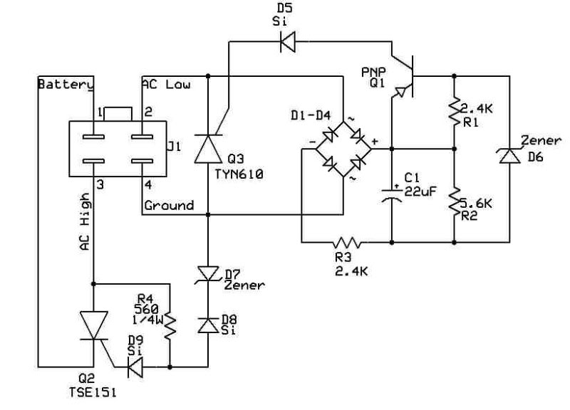
I took this one apart and traced out the internal connections. Q2 is the rectifier part, and D7 is the voltage reference used to turn Q2 on and off to maintain the proper voltage on the battery. Q3 and all that circuitry to the right forms a crude AC regulator that maintains an AC voltage for running lights. Curiously many new quads don't use an AC powered light system so this stuf is all redundant - left over and copied from Honda days a long time ago.
Just to make sure your quad has the most common stator measure the resistance of the yellow and white wires to ground with the regulator unplugged. If you see low ohms from both wires to ground (and low ohms between the two wires too) then this is the type of stator you have. If you see infinite ohms to ground, but low resistance between the yellow and white wires then you have a different stator - in which case a different regulator design is used.
On an alternator (like a ford car or truck) the magnetic field that spins past, and generates voltage in, the battery charge winding is made by passing current into another coil of wire (the field coil or rotor coil). The stronger this field is the more voltage is generated, and the weaker the field less voltage is generated. This field strength is adjusted by the voltage regulator controlling the current fed to the field (rotor) coil. Thus the output voltage on the far side of the rectifier diodes feeding the battery can be precisely controlled by servo'ing the field current up and down (and therefor adjusting the magnetic field cutting past the battery charge windings).
In a stator system (like your quad) the magnetic field that spins past the battery charge windings comes from permanent magnets embedded inside the flywheel housing. They cannot be adjusted up or down in magnetic strength. Thus the stator is always generating voltage at maximum output. After being rectified inside the rectifier regulator, it is the responsibility of the regulator to limit the voltage to the battery. There are many different ways this is accomplished. Different regulators may use drastically different circuitry to do this
So does your chopper have an alternator system? Or a stator system? I don't see how a ford regulator as depicted in your diagram can possibly work in a stator based charge system. The "F" output cannot control the magnetic field in the stator because they are permanent magnets instead of a coil forming an electromagnet.
Here is a schematic of a typical 2 pole single phase regulator/rectifier used on 110cc quads. I believe this is the regulator for the most common stator type on 110cc quads (but there are others).
I took this one apart and traced out the internal connections. Q2 is the rectifier part, and D7 is the voltage reference used to turn Q2 on and off to maintain the proper voltage on the battery. Q3 and all that circuitry to the right forms a crude AC regulator that maintains an AC voltage for running lights. Curiously many new quads don't use an AC powered light system so this stuf is all redundant - left over and copied from Honda days a long time ago.
Just to make sure your quad has the most common stator measure the resistance of the yellow and white wires to ground with the regulator unplugged. If you see low ohms from both wires to ground (and low ohms between the two wires too) then this is the type of stator you have. If you see infinite ohms to ground, but low resistance between the yellow and white wires then you have a different stator - in which case a different regulator design is used.
here is a wiring diagram
granted its for a 3 phase system
now I need to know again what wires are coming out of the alternator. Is it the yellow and the white one? does the yellow wire come off the stator? there is only 4 wires on that piece of poop. this cant be hard for me to figure out. with your help
black ?
white ?
yellow ?
red ?
granted its for a 3 phase system
now I need to know again what wires are coming out of the alternator. Is it the yellow and the white one? does the yellow wire come off the stator? there is only 4 wires on that piece of poop. this cant be hard for me to figure out. with your help
black ?
white ?
yellow ?
red ?
#17
05-30-2011, 12:22 AM
Electrical Expert
Likes High Voltage In The Tub!
Likes High Voltage In The Tub!
Join Date: Dec 2008
Location: Tracy, California, USA
Posts: 3,260
Likes: 0
Received 12 Likes
on
12 Posts
now I need to know again what wires are coming out of the alternator. Is it the yellow and the white one? does the yellow wire come off the stator? there is only 4 wires on that piece of poop. this cant be hard for me to figure out. with your help
black ?
white ?
yellow ?
red ?
black ?
white ?
yellow ?
red ?
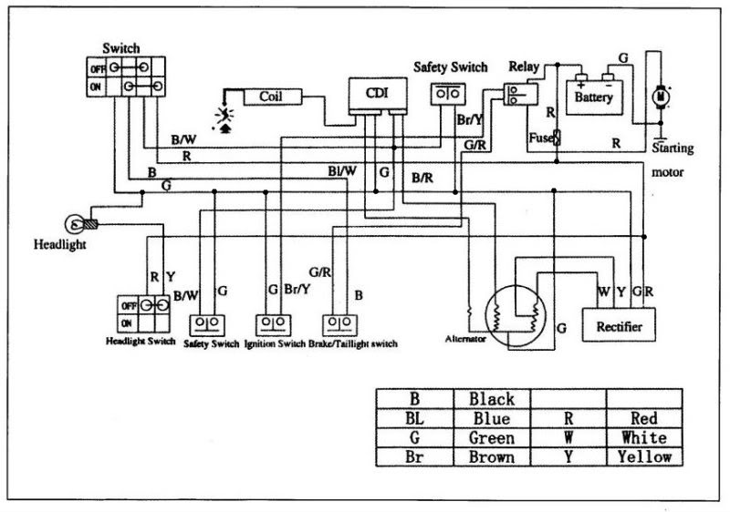
Note the yellow and white wires coming off the stator (incorrectly labeled alternator) battery charge winding. Also note how they are two taps at the high end of the coil, with the other end grounded.
You must also have a trigger wire coming of the stator (usually blue/white), and usually a ground (green or black). You may or may not have the moderately high voltage CDI power winding. If your CDI has five pins you must have this winding. If your CDI has four pins then you may not have the winding. This wire is usually Black/Red.

Thread
Thread Starter
Forum
Replies
Last Post
Currently Active Users Viewing This Thread: 1 (0 members and 1 guests)