2008 Linhai 260cc keep losing spark Help Lynn!
#1
 09-01-2012, 04:58 PM


Join Date: Sep 2012
Posts: 6
Likes: 0
Received 0 Likes
on
0 Posts
I have a linhai 260 cc I obtained through trader, have had this thing pulled apart more times than I can count electrically, check stator 215 ohms, had a bad connection at stator where it meets the harness instaled crimp butt connectors, have tested ignition coil resistances, they check fine. I had a bad connection at my cooling fans repaired those, started it up today since it is the holiday weekend , made it to the end of driveway, cough cough sputter backfire.. no spark again. this is pic of my CDI Cdi 10 for Chinese 300cc Atvs - Cd270-10 - Cdi Boxes - Electrical Parts - - Chinese Atv Parts Cdi I am using a fieldpiece meter 10 meg input impedance
#2
09-02-2012, 09:25 PM

Electrical Expert
Likes High Voltage In The Tub!
Likes High Voltage In The Tub!
Join Date: Dec 2008
Location: Tracy, California, USA
Posts: 3,260
Likes: 0
Received 12 Likes
on
12 Posts
How many wires go to your CDI, and what are the colors?
What model Fieldpiece meter are you using (so I can look it up and follow along with your measurements).
Have you looked over this very recent thread:
http://forums.atvconnection.com/chin...-no-spark.html
Note in this thread the Buyang 300cc wiring diagram seems to match Dona's Linhai 300cc quad more closely then the two other Linhai 260/300cc wiring diagrams posted later from the Linhai service manual. Look at those wiring diagrams and see which one matches your quad the best. The best way to do that is look at the number of wires, and the wire colors, at each connector involved with ignition (ignition switch, kill switches, speed limiters, ignition coils, and stator). That's why I started off this post with how many wires on the CDI and what are the colors....
You mentioned that the ignition coil resistance measured fine. OK, but I would be a lot more confident about that if you would instead post the actual values that your measured, and what criteria you used to determine it was good.
Remember that you are trying to fix an intermittent problem. What that means is that *all* diagnostic tests have to done while the quad is not working. If you measure the bad component/connection/wire while the ignition system is working then you'll skip right over the problem and get frustrated and lost. Make sure that you have no spark, do a diagnostic test, and then make sure again that you *still* don't have spark.
#3
09-04-2012, 09:04 PM
Join Date: Sep 2012
Posts: 6
Likes: 0
Received 0 Likes
on
0 Posts
#4
09-05-2012, 11:30 PM
Electrical Expert
Likes High Voltage In The Tub!
Likes High Voltage In The Tub!
Join Date: Dec 2008
Location: Tracy, California, USA
Posts: 3,260
Likes: 0
Received 12 Likes
on
12 Posts
Cooling the CDI down with freon is a good troubleshooting technique. I agree with your diagnosis. I can't help with the pricing issue. One thing that is nice about the generic "me too" CDIs that most chinese put in their machines is that they are plentiful and cheap. The less common CDIs cost more because there is less requirement fro them, and less suppliers. The existing handfull of suppliers charge more because they can.
#5
09-07-2012, 11:19 AM
Join Date: Sep 2012
Posts: 6
Likes: 0
Received 0 Likes
on
0 Posts
Well lynn I did my apprenticeship at a Tv repair shop back in 1998, sadly I am not as familiar with swapping CDI's as I am looking up the parameters of an output transistor in a Darlington pair and making the swap. If I send you the 5 wire colors from the CDI and their destination can you inform me if it is AC or DC triggered and possibly what I could use, trust me I won't hold it as gospel but a chance to use a 14.00 CDI is worth a bit of gamble to me.
#6
09-07-2012, 11:53 PM
Electrical Expert
Likes High Voltage In The Tub!
Likes High Voltage In The Tub!
Join Date: Dec 2008
Location: Tracy, California, USA
Posts: 3,260
Likes: 0
Received 12 Likes
on
12 Posts
Earlier there was a link to another Linhai 300cc problem. In that link there was a 300cc buyang diagram, and two Linhai 260/300cc diagrams right out of the service manual. You might want to see if they match your quad wiring. Note, though, that all of those diagrams show a coil wiring scheme quite different from the generic chinese scheme that is so common. Note how the primary ignition coil winding is driven from the CDI, but the other side of the ignition coil goes to switched, fused, +12 volts instead of ground. Your CDI may not even be a CDI. It may be a completely different system.
All ignition systems have a series resonant circuit on the primary side which consists of the inductance of the ignition coil primary coupled with a capacitor somwhere (inside the 'CDI' in your case). Then the ignition system charges up one of those two with energy, and at the trigger time lets it go. It rings at the resonant frequency which is designed to match the resonant frequency of the ignition coil secondary winding - which is a parallel resonant circuit consisting of the inductance of the secondary widing and the distributed (parasitic) capacitance across the windings. You get maximum transfer of energy that way up to the point that the plug fires. After that different ignition systems perform differently.
The old kettering style points/plug/condensor(capacitor) charged up the ignition coil primary with a magnetic field, while the CDI charges up a capacitor with a few hundred volts. Do one or the other, then at trigger time let them ring back and forth. Based on you wiring diagram your ignition module could be doing either...
The coil and the CDI (or ??? in your case) are a tuned pair. I'm worried that strikingly different wiring scheme implies a possibly differnent ignition topology. At the very least you would have to change the ignition coil too, and redo a lot of wiring. Then we have to contemplate the ignition advance curves. Does your 260cc 4 stroke engine use the same advance curves (this is built into the ignition module) as a 150cc machine 4 stroke? I don't know.
To me it does not seem the possible benefits (cost) outweigh the risks (massive effort resulting in total failure). I'm a cheap man, but I'd spend the $90.
Your CDI is DC powered on all three wiring diagrams referenced above BTW.
#7
09-10-2012, 01:33 PM
Join Date: Sep 2012
Posts: 6
Likes: 0
Received 0 Likes
on
0 Posts
Thanks Lynn that actually helped allot I will let you know what I did at the end of this post. Yeah, if resonance (Z) is the point of ignition and the variable is Frequency (RPM's) then resonance or Z will take place at the cross of Xc and Xl with frequency being the variable. Impedance shall we say. worked allot with this in band pass, stop, and notch filters.
Okay, so what did I do? The PS3 had a problem with solder connections on their graphics processor, if you Google it you will see everything from hair dryers to ovens trying to remedy this problem. With so many electronics coming from overseas where lead is prohibited the connections on allot of these devices become brittle and create rings around the pads on solder connections. I applied this theory to the CDI I was currently having problems with, figured I didn't have much to lose so I heated it up to around 1200 degrees F slowly and placed in sand to allow to cool slowly. so far 3 days 2 tanks of gas and not one cough, sputter or die.. we will see what happens. the heat I actually applied to the epoxy covering on the back working in small circles, never heated the front plastic.
Okay, so what did I do? The PS3 had a problem with solder connections on their graphics processor, if you Google it you will see everything from hair dryers to ovens trying to remedy this problem. With so many electronics coming from overseas where lead is prohibited the connections on allot of these devices become brittle and create rings around the pads on solder connections. I applied this theory to the CDI I was currently having problems with, figured I didn't have much to lose so I heated it up to around 1200 degrees F slowly and placed in sand to allow to cool slowly. so far 3 days 2 tanks of gas and not one cough, sputter or die.. we will see what happens. the heat I actually applied to the epoxy covering on the back working in small circles, never heated the front plastic.
Trending Topics
#8
09-11-2012, 10:02 PM
Electrical Expert
Likes High Voltage In The Tub!
Likes High Voltage In The Tub!
Join Date: Dec 2008
Location: Tracy, California, USA
Posts: 3,260
Likes: 0
Received 12 Likes
on
12 Posts
... Yeah, if resonance (Z) is the point of ignition and the variable is Frequency (RPM's) then resonance or Z will take place at the cross of Xc and Xl with frequency being the variable. Impedance shall we say. worked allot with this in band pass, stop, and notch filters....
If the engine is running at 6000 RPM the trigger rate is only 100 times per second. Big deal... That's a long way from 30 KHz. Every ignition pulse is the same regardless of the engine RPM.
........Okay, so what did I do? The PS3 had a problem with solder connections on their graphics processor, if you Google it you will see everything from hair dryers to ovens trying to remedy this problem. With so many electronics coming from overseas where lead is prohibited the connections on allot of these devices become brittle and create rings around the pads on solder connections. I applied this theory to the CDI I was currently having problems with, figured I didn't have much to lose so I heated it up to around 1200 degrees F slowly and placed in sand to allow to cool slowly. so far 3 days 2 tanks of gas and not one cough, sputter or die.. we will see what happens. the heat I actually applied to the epoxy covering on the back working in small circles, never heated the front plastic.
Then you said " so I heated it [the CDI] up to around 1200 degrees F ". No way did you do this. If you heated up the CDI to 1200 degrees F the CDI would be a lump of charcoal. I have to speak up, because others will read your post and decide to try this and totally wreck a perfectly good ($$$) CDI when all they have wrong is a bad connection. Please be clear in your posts. I suspect you have a heat gun that puts out a maximum of 1200 degrees at the outlet port, and you waved this over your CDI in some manner. This is a far cry from heating up the entire CDI to 1200 degrees.
So are you attempting to claim that you "reflowed" the solder on the PCB inside the CDI by heating the PCB through a layer of epoxy, without flux? I don't think so. I don't know what you are actually doing but I susepct you're fooling yourself.
#9
09-11-2012, 10:10 PM
Electrical Expert
Likes High Voltage In The Tub!
Likes High Voltage In The Tub!
Join Date: Dec 2008
Location: Tracy, California, USA
Posts: 3,260
Likes: 0
Received 12 Likes
on
12 Posts
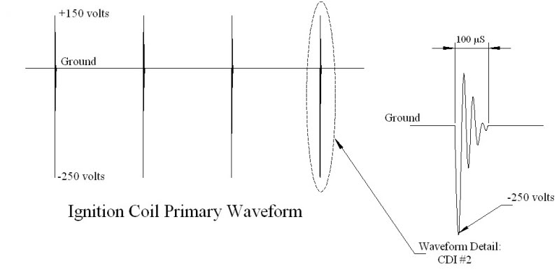
I forgot to mention in my previous post that the ignition waveforms I posted are for the generic "me too" commonly available 4 stroke CDIs - which may not apply to your quad. Yours is wired differently, and I'm worried that if you try to substitute a different CDI they may not be compatible (as I mentioned before).
But I need to make clear that the waveforms I posted may not apply to a working Linhai 260cc machine with the stock CDI at all. I don't know. I need to state this because search engines are going to bring a lot people here down the road...
But I need to make clear that the waveforms I posted may not apply to a working Linhai 260cc machine with the stock CDI at all. I don't know. I need to state this because search engines are going to bring a lot people here down the road...

Thread
Thread Starter
Forum
Replies
Last Post
Hankey Pankey
Performance Mods and Project Quads
1
07-31-2015 05:50 PM
Hankey Pankey
Technical and How-To Articles
0
07-29-2015 10:57 PM
Currently Active Users Viewing This Thread: 1 (0 members and 1 guests)