Regulator Out Put Voltage / Connection ??
#1
 04-08-2010, 04:58 PM


Join Date: Apr 2010
Posts: 7
Likes: 0
Received 0 Likes
on
0 Posts
Hi.
I have a Lifan 200cc quad with an 163ML-2N engine on which (long story..dont ask) I have fitted a new stator, CDI, Regulator/Rectifier, Battery and Coil !
As this is my first quad Im kinda trial and error on the whole thing yet (with some help) have managed to get it to turn over and run yet I just cant work out the connections on the regulator???
I have 3 cables that I am lost with : 1x Red, 1x Black and 1x Green.
Does the Red cable connect to the switch side of the ignition or to the permanent live ??????
Also where do the green and black ones go !!!!!!!
When I use a multi-metre from the 'out' side of the regulator on the Red cable to the battery negative terminal I get a +/- 6V reading, yet between the Red cable and the battery positive terminal I get +/-13 V.
Can anyone please help, I have attached some piccies of the cables in question and have many more of the bits n pieces if you need to see em !
#2
04-09-2010, 12:54 AM

Electrical Expert
Likes High Voltage In The Tub!
Likes High Voltage In The Tub!
Join Date: Dec 2008
Location: Tracy, California, USA
Posts: 3,260
Likes: 0
Received 12 Likes
on
12 Posts
If I understand your post correctly, you have a 6 pin regulator - three yellow wires that go to the stator, and three more (black/green/red) that need to wire into the battery and other stuff. Am I right?
Do you have an automatic choke? These are usually powered off one phase of the stator directly, or off some unregulated equivalent out of the rectifier. Automatic choke power is unregulated since it will be higher with higher engine RPM. Thus if you start up your quad and let it idle the engine and the choke both warm up slowly (the choke closes as it gets warmer). If you start up your quad and take off down the trail they both warm up fast.
With the rectifier completely disconnected from the battery it is meaningless to try and measure voltages between them (rectifier and battery). When unplugged they are not connected in any way except through stray capacitances.
Instead, with the engine running measure the DC voltage between the red and black wire, and then the red and green wire. Do either pair look like they have 13-15 volts DC between them? Those will be the battery charge wires. The plus side (red) can be wired on either side of the ignition switch. The diodes in the rectifier keep any current from flowing out of the battery and through the rectifier, so either plan works. Wiring to the switched side of the ignition switch adds redundancy since now the switch *and* the diodes are blocking battery current from draining the battery.
#3
04-09-2010, 10:19 AM
Join Date: Apr 2010
Posts: 7
Likes: 0
Received 0 Likes
on
0 Posts
Hi Lynn
Firstly thanks for the reply.
You are correct it has 6 cables, 3 x yellow to stator and black+green+red that go....... I dont know where.
The choke is manually controlled via a switch on the handle bars so I am guessing this is classed as a manual one?
I will check the voltage between red+black and then red+green this evening and post back as Im at work at the moment.
Am I reading your reply correctly in that it would be better if the red was connected to the permanent live as opposed to the switched side ?.
What is adding to my confusion is that your reply suggests that we need 1x to positive or battery and 1x to negative yet I have 3 cables so once we establish which pair are the charging ones what is the 3rd one for?
Once again many many thanks for the help on this is truely appreciated. As said above I will test the pairs this evening and post back here but as Im in the UK I guess the time difference could make this protracted .
Best Regards
Last edited by dirtboyuk; 04-09-2010 at 10:24 AM. Reason: Omission of further dumb question!
#4
04-09-2010, 02:37 PM
Join Date: Apr 2010
Posts: 7
Likes: 0
Received 0 Likes
on
0 Posts
Hi Lynn
Herwith results but not good reading !!
Engine running on idle :-
Red to Black = Zero Volts
Red to Green = 6.7 Volts
Green to Black = Zero
Across battery (which had just been charged using a power pack) = 12.8 Volts.
Have we wired something wrong during the re-wire/part replacement or is it a wrongly rated regulator/rectifier (IE were we sold a 6 volt one instead of a 12 volt??) The regulator/rectifer was for a 200cc quad...did they make a 200cc Lifan with a 6 volt system??
Common sence is telling me that it cant be wired wrong, yet what would be only giving 6 volt. Is it possible that we have a wrong stator as in my limited understanding that is the source of the power to the reg/rect.
The stator was 100% identical to the old item so I'm guessing that's not the issue. Is it possible to connect this wrong such that it would cause the low output?
Sorry for the rambling questions yet my knowledge is very very limited and too my budget hence buying an old-dog of a quad. Im just really at a loss with this now
#5
04-10-2010, 12:52 AM
Electrical Expert
Likes High Voltage In The Tub!
Likes High Voltage In The Tub!
Join Date: Dec 2008
Location: Tracy, California, USA
Posts: 3,260
Likes: 0
Received 12 Likes
on
12 Posts
I did some looking and this is more complicated than I thought. Some links to ponder:
BuggyNews Buggy Forum • View topic - NST 250cc cart wiring issues
In this link there is another link to Buggydepot.com.
Note that the buggydepot regulator has seven wires - one is for the autochoke, while the others match your wire colors exactly.
To make thinks even more interesting look at the following wiring diagram for a VBike 4VS quad (all credit to Mach1JE79 who hand traced his whole quad wiring):
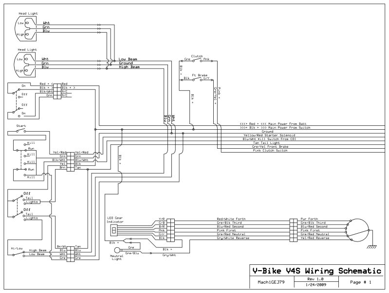
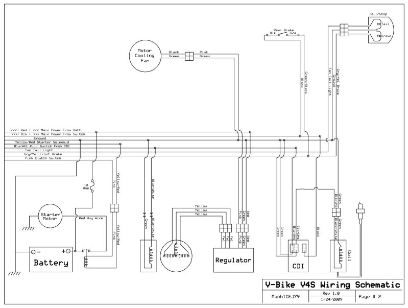
Note that it too has a 6 pin 2 connector regulator with a pink wire driving a cooling fan instead of the choke in my original scenario. Its looking like there isn't a single solution to how any old 6 wire regulator is wired up.
Maybe you also have multiple problems. Unplug the stator connector that has three yellow wires. Use a meter to measure all three yellow wire resistances on the stator side to ground. I think they should be open (infinite resistance). If they aren't, what are the resistances to ground on each wire?
If they are open then start up the quad. Measure the AC voltage between each yellow wire and the other yellow wires (on the stator - not on the wiring harness to the rest of the quad). What do you measure? Do not measure voltages from each yellow wire to ground.
What I'm trying to have you measure is the output of the three phase stator windings before they go to the rectifier/regulator. I'm looking for clues...
BuggyNews Buggy Forum • View topic - NST 250cc cart wiring issues
In this link there is another link to Buggydepot.com.
Note that the buggydepot regulator has seven wires - one is for the autochoke, while the others match your wire colors exactly.
To make thinks even more interesting look at the following wiring diagram for a VBike 4VS quad (all credit to Mach1JE79 who hand traced his whole quad wiring):
Note that it too has a 6 pin 2 connector regulator with a pink wire driving a cooling fan instead of the choke in my original scenario. Its looking like there isn't a single solution to how any old 6 wire regulator is wired up.
Maybe you also have multiple problems. Unplug the stator connector that has three yellow wires. Use a meter to measure all three yellow wire resistances on the stator side to ground. I think they should be open (infinite resistance). If they aren't, what are the resistances to ground on each wire?
If they are open then start up the quad. Measure the AC voltage between each yellow wire and the other yellow wires (on the stator - not on the wiring harness to the rest of the quad). What do you measure? Do not measure voltages from each yellow wire to ground.
What I'm trying to have you measure is the output of the three phase stator windings before they go to the rectifier/regulator. I'm looking for clues...
#6
04-10-2010, 11:25 AM
Join Date: Apr 2010
Posts: 7
Likes: 0
Received 0 Likes
on
0 Posts
Hi Lynn
I tried the test you suggested and got the open readings through the strator for ressistance without the engine running. This was the same across all 3 yellow cables.
With the engine running and the tester set for AC we got 18/19/18 volt readings between the various combinations of yellow wires. Is this high emough as I thought I had read (in one of my numerous searches of the net ) that the stator should out put +/- 30 volts and upwards ???
Or is 18/19 volts okay?
Many thanks for you help with this its really appreciated
Best Regards
Dirtboy
#7
04-10-2010, 10:06 PM
Electrical Expert
Likes High Voltage In The Tub!
Likes High Voltage In The Tub!
Join Date: Dec 2008
Location: Tracy, California, USA
Posts: 3,260
Likes: 0
Received 12 Likes
on
12 Posts
I think that having the same readings on three independant coils means that the voltages are OK. And there should not be any problem for a regulator to take 18 volts AC between phases 120 degrees apart and make 14 volts DC to charge the battery.
Like you, I recall people claiming 29 (or so) volts between phases, but I still think 18 volts AC is OK. Like I said, three independant coils measure the same. If you had reported 29 volts, 30 volts and 2 volts, well that would be a different story.
So what happens to the voltages between the stator output wires when the engine speed increases (voltage regulator is still unplugged for this test, same as it was during the last one)? It should be linear with engine speed. 18 volts at 1900 RPM should be 36 volts at 3800 RPM. If you see this then this would be a further indication that everything is working normally at the stator output.
Maybe you just have a bad voltage regulalator...
Trending Topics
#8
04-11-2010, 03:46 AM
Join Date: Apr 2010
Posts: 7
Likes: 0
Received 0 Likes
on
0 Posts
Hi Lynn
Again thanks for the reply.
I will check today if the out put increases with engine speed and let you know. If it doesnt what would your thoughts be on this ?
I am in agreement with you that i suspect either the reg is faulty or for a 6 volt system. Is there a test for the regulator to establish if it is faulty as opposed to the wrong item ??
On Monday ( its now sunday am in UK) I will ring the suppliers and tell them that the stator outputs 19V yet the reg only provides 6 volt and post back with thier comments.
I feel much happier now that youhave said the stator out put is ok as it suggest that the problem is the rect/reg which should be easy to correct by getting a replacement.
Best Regards
Dirtyboy
#9
04-11-2010, 08:21 AM

I also got a new lifan 163ML-2N engine to replace the bad 110cc engine on my boy's go cart. When I got the engine it didn't have a cdi box and have not been able to find the right one. Do you know were or what kind I need. I bought 2 cdi boxes that looked like they were correct according to the wiring diagram with the new engine but failed to make spark. The cdi box on the old engine is definatly the wrong type. The wires from the stator is on the engine with a plug on it but it does not have the full wiring harness than would have the plug for the cdi box. So I'm not 100% sure what the plugs looks like (wiring diagram shows 2 plugs). I don't know what model atvs this engine was used on or maybe I could search for a cdi for that particular atv. And info would be greatly appreciated. Thanks.
418mustang@gmail.com
418mustang@gmail.com
#10
04-11-2010, 03:03 PM
Join Date: Apr 2010
Posts: 7
Likes: 0
Received 0 Likes
on
0 Posts
Hi Lynn.
Tested again the 3 yellow wires direct from the stator and as before each combination provided 19 volts. I then increased to approx double the revs and the readings all increased to 39 volts , again regardless of combination.
From this i am guessing that the staor is working fine and that the prob lies with the reg/rect, either wrong item or from a faulty batch ???
Do you have any views on this as I plan to speak to the suppliers on Monday morning (currently Sunday evening in UK)?
Hi 418 Mustang.
I got mine from a UK company and the item was referenced by them as a " 250cc Kazuma " so it may be worth a try?? If you want I can let you have thier details yet do not know if they ship to US.
Dirtboy