
giovanni 200cc...NO SPARK...Pls Help
 Mar 16, 2010 | 11:02 AM
#11

Electrical Expert
Likes High Voltage In The Tub!
Likes High Voltage In The Tub!
Joined: Dec 2008
Posts: 3,260
Likes: 14
From: Tracy, California, USA
Danmp,
What kind of quad is this?
How many pins where on your old CDI? 5? 6?
If you had a 6 wire CDI (2 pin and 4 pin dual connector) do you know if it is AC powered or DC powered? We can find out if you don't know, but you'll need a meter.
I'll look for info on the performance CDI. Do have a link to a web site showing how to install it?
Mar 16, 2010 | 11:35 AM
#12

Weekend Warrior
Joined: Mar 2010
Posts: 10
Likes: 0
From: Quebec, Canada
For the ac or dc I don't know and there is no information on the cdi.
For the old cdi that's a great question I believe it was a 5 pin.
My atv is a copy of the gio beast 200cc , but the engine is a 250 cc, it's all the same component, same cdi, carbu and all other thing.
Normally the cdi was plug and play, but the connector was a little bit loose , so a connect the cdi directly. The atv was working just before the winter... I mean sometime the atv was working, sometime not. And now I don't get any power on the spark plug
Mar 16, 2010 | 08:47 PM
#13
Weekend Warrior
Joined: Mar 2010
Posts: 10
Likes: 0
From: Quebec, Canada
Below I posted a pic of my cdi. I found something strange. When I try to start, some power get out of the two green wire, but when I connect it to it's black wire( only one green, because the second is not supposed to be use) after the black wire ( of the atv) and the green( of the cdi) are connected, when I check the power there is no power ( take note that I check this with a illuminated testor) This black wire goes to a branch of 3 or 4 other black wire.
An other thing I've noticed, it's when I just touch rapidly and few times the black and green togheter, I got some power on my black with a yellow stripe( this one go toward my spark plug)
Please excuse my english , this is not my primary language.

An other thing I've noticed, it's when I just touch rapidly and few times the black and green togheter, I got some power on my black with a yellow stripe( this one go toward my spark plug)
Please excuse my english , this is not my primary language.
Mar 17, 2010 | 12:04 AM
#14
Electrical Expert
Likes High Voltage In The Tub!
Likes High Voltage In The Tub!
Joined: Dec 2008
Posts: 3,260
Likes: 14
From: Tracy, California, USA
I tried to find info on the Casoli Moto CDI. I didn't find anything useful.
Your pictures were very helpful. The casoli connector shows the standard 2 and 4 pin dual connector setup, so that is a start. Your quad is using a standard color code for the CDI wiring, so assuming a standard pinout for your casoli cdi (based on using the standard connector), I think your pictures show that the CDI is wired correctly.
But there is a big problem with standard (non-performance) 2 and 4 pin dual connector CDIs: Some are powered with 12 volts DC. Most are powered with moderately high voltage AC. And they look identical. How is your quad wired? You have to put in the correct CDI or it won't work.
DC powered CDIs will not work in an AC powered quad. AC CDIs will not work in a DC powered quad. In fact, if you put a standard AC powered CDI in a DC powered quad, it blows up in a spectacular fashion. Smoke, fire, loud noises, and a big new hole in your new CDI. I don't know what happens with an AC powered performance CDI plugged into a DC powered quad.
You're using an "illuminated testor" to do measurements. This is often referred to as a "test light". They are a complete waste of time. If someone gave me one as a present I would be polite and gracious, but as soon as they were not looking I'd chuck in the trash. What good is a device that gives only an ON or OFF answer? Life is complicated, and there is a broad span between on and off, and AC and DC, and fast and slow. Throw that thing away and buy a voltmeter! Voltmeters give you much more information, and they are really inexpensive these days (even cheaper than test lights).
Disconnect the CDI and take your new voltmeter and measure the voltage on the Red/Blk wire to the CDI in the wiring harness (loom) with the ignition switch turned on, and the engine stopped. What do you measure? If it is 12 volts DC then your quad is wired for a DC powered CDI. If you get zero volts DC, then crank you quad and measure AC voltage on the same wire. If you get 50-80 volts AC then your quad is a AC powered quad.
Since most 6 pin CDI quads are AC powered, I'm betting that the casoli CDI is also AC powered. If you find your quad is DC powered, and you wired in your AC powered CDI, it may be blown up. I don't know. Try putting back in your original CDI, or buying the proper (AC or DC powered) standard CDI off eBay (or wherever) and get the quad running. Then revisit the Casoli CDI.
I had no trouble understanding your english at all .
.
Your pictures were very helpful. The casoli connector shows the standard 2 and 4 pin dual connector setup, so that is a start. Your quad is using a standard color code for the CDI wiring, so assuming a standard pinout for your casoli cdi (based on using the standard connector), I think your pictures show that the CDI is wired correctly.
But there is a big problem with standard (non-performance) 2 and 4 pin dual connector CDIs: Some are powered with 12 volts DC. Most are powered with moderately high voltage AC. And they look identical. How is your quad wired? You have to put in the correct CDI or it won't work.
DC powered CDIs will not work in an AC powered quad. AC CDIs will not work in a DC powered quad. In fact, if you put a standard AC powered CDI in a DC powered quad, it blows up in a spectacular fashion. Smoke, fire, loud noises, and a big new hole in your new CDI. I don't know what happens with an AC powered performance CDI plugged into a DC powered quad.
You're using an "illuminated testor" to do measurements. This is often referred to as a "test light". They are a complete waste of time. If someone gave me one as a present I would be polite and gracious, but as soon as they were not looking I'd chuck in the trash. What good is a device that gives only an ON or OFF answer? Life is complicated, and there is a broad span between on and off, and AC and DC, and fast and slow. Throw that thing away and buy a voltmeter! Voltmeters give you much more information, and they are really inexpensive these days (even cheaper than test lights).
Disconnect the CDI and take your new voltmeter
and measure the voltage on the Red/Blk wire to the CDI in the wiring harness (loom) with the ignition switch turned on, and the engine stopped. What do you measure? If it is 12 volts DC then your quad is wired for a DC powered CDI. If you get zero volts DC, then crank you quad and measure AC voltage on the same wire. If you get 50-80 volts AC then your quad is a AC powered quad.Since most 6 pin CDI quads are AC powered, I'm betting that the casoli CDI is also AC powered. If you find your quad is DC powered, and you wired in your AC powered CDI, it may be blown up. I don't know. Try putting back in your original CDI, or buying the proper (AC or DC powered) standard CDI off eBay (or wherever) and get the quad running. Then revisit the Casoli CDI.
I had no trouble understanding your english at all
.
Mar 17, 2010 | 08:55 AM
#15
Weekend Warrior
Joined: Mar 2010
Posts: 10
Likes: 0
From: Quebec, Canada
Wow , thank you for all this information. I tested my atv this morning and I got 0V with the engine stopped, and more than 50-80 v ac... It's an old tester with a needle, so I'm not sure of result, it show around 400 v ac if I read correctly
Something is strange, My original cdi is the same one the first page of this topic , and on the gio site I asked if the 250 if this cdi can go on a 250cc and everyone answered yes
For Now I cannot test my old cdi because I forget it outside and I passed the lawnmower on it ...
I'm waiting for the new one in the next weeks.
Mar 17, 2010 | 10:20 AM
#16
Weekend Warrior
Joined: Mar 2010
Posts: 10
Likes: 0
From: Quebec, Canada
Ok, if I understanded, the:
The black - yellow is for the coil
the green is for the ground
The other green is for the auto choke ( my atv don't have it and this one is actually connected to nothing)
The black and white is for the kill switch( I tried to don't connect it to verify if my kill switch was the problem)
The black and red is for the power coming from the alternator
The blue and white is connected to the alternator
I don't know if it's normal, but I don't get any power on the blue and white wire even when I start.
And something strange is when I touch rapidly and few times the green wire to the cable on the atv ground I got some power on the yellow and black wire, but I don't have nothing when they are togheter.
I don't understand anything to this problem
Mar 17, 2010 | 01:26 PM
#17
Weekend Warrior
Joined: Mar 2010
Posts: 10
Likes: 0
From: Quebec, Canada
This is a picture of my voltmeter, i'm not sure how it's work
Edit: I got what you said, around 50-80 ac volts on the black and red at startup. I don't have anything on the blue and white... with the setup 15V and AC-V on the voltmeter
An other thing to know , my wires around the entry of the stator have been "crushed" by the chain is it possible that the wires inside have been damaged by this? And if yes how to access to this? I tried , but even with all bolt remove, I cannot have access to the inside .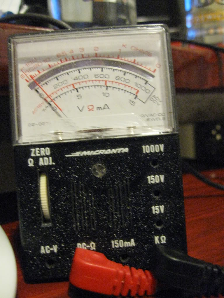
Mar 18, 2010 | 12:30 AM
#19
Electrical Expert
Likes High Voltage In The Tub!
Likes High Voltage In The Tub!
Joined: Dec 2008
Posts: 3,260
Likes: 14
From: Tracy, California, USA
My comments in red embedded in your text (I agree with your comments unless I respond in red):
Ok, if I understanded, the:
The black - yellow is for the coil
the green is for the ground
The other green is for the auto choke ( my atv don't have it and this one is actually connected to nothing) No, I think both greens should be ground. The auto choke (if you had one) would be connected to one of your battery charging stator windings. This would have nothing to do with the CDI or ignition
The black and white is for the kill switch( I tried to don't connect it to verify if my kill switch was the problem)
The black and red is for the power coming from the alternator
The blue and white is connected to the alternator This is the trigger wire for the CDI. This tells the CDI to fire the plug *NOW*.
I don't know if it's normal, but I don't get any power on the blue and white wire even when I start. The voltages here are a pair of narrow spikes (plus and minus) that are 5 volts (or so high) but because they occur at such a low duty cycle you meter will read a really low voltage like 0.3 volts AC at cranking speeds
And something strange is when I touch rapidly and few times the green wire to the cable on the atv ground I got some power on the yellow and black wire, but I don't have nothing when they are togheter. Your earlier measurements suggest that the CDI is AC powered. Thus, all energy to run the CDI comes from a turning engine. If the engine is stopped (not turning) then there is no power source to the CDI and so there can be no output of any kind. This is an important question: Did you see this "power" on the yellow-black wire (while shorting the green wire to ground) while the engine was stopped, or did this happen while the engine was being cranked with the starter? If you saw this with the engine stopped then you have made a measurement error somewhere. It simply cannot be. If you saw this with the engine being cranked with the starter, then the next question is: Do you get a spark while doing this?
I don't understand anything to this problem
Mar 18, 2010 | 12:37 AM
#20
Electrical Expert
Likes High Voltage In The Tub!
Likes High Voltage In The Tub!
Joined: Dec 2008
Posts: 3,260
Likes: 14
From: Tracy, California, USA
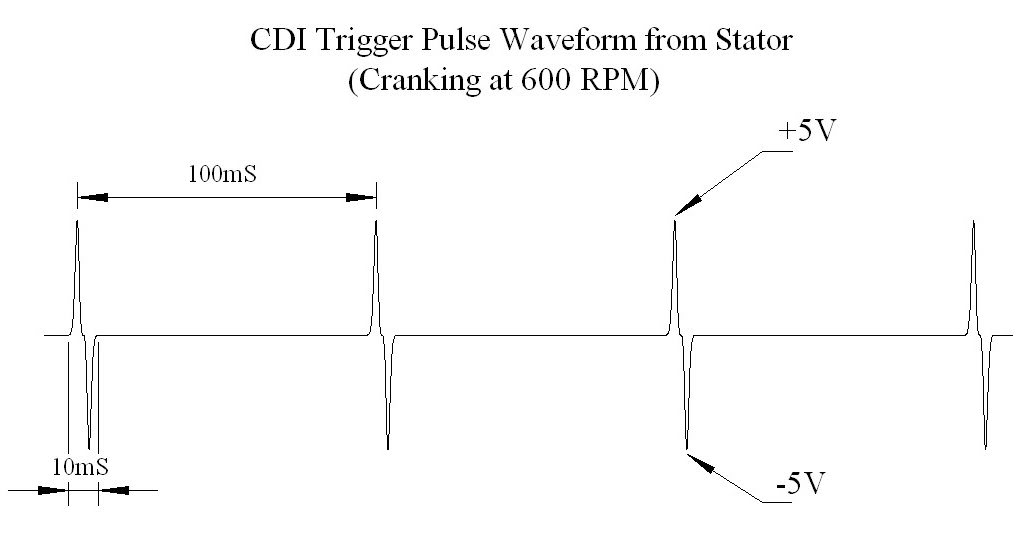
Actually I posted earlier that the voltages were +/- 12 volts. That's at idle - not cranking. I'll try to go back edit that post to correct the error...