No spark - kids upset
#31
 10-23-2010, 01:26 AM


Join Date: Sep 2010
Posts: 33
Likes: 0
Received 0 Likes
on
0 Posts
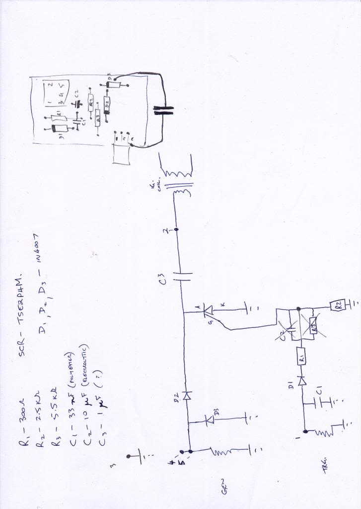
Righty-o hopefully this works, and hopefully you can read it. Ignore the cap and resistor that are crossed out and the new line I drew to short them out, I compared the circuit to the silicon chip basic circuit and I think you could leave them out.
The large dots with a number beside them are the plug pins. I numbered them left to right top to bottom, like this.
1 - 2
3 4 5
The drawing out to the right was the board layout, as I may reuse the board with new components.
Its very basic thats for sure. The resistors values etc were gained using my fluke. I checked the datasheet on the SCR and it was 2 or 3 amps which I'm thinking maybe the problem. The resistors were all the small blue type 1/4watt I think.
Anyway see what you think, I am going to put the circuit into electronics workbench when I get a chance and see if I can get a working simulation.
#32
10-23-2010, 09:25 PM

Electrical Expert
Likes High Voltage In The Tub!
Likes High Voltage In The Tub!
Join Date: Dec 2008
Location: Tracy, California, USA
Posts: 3,260
Likes: 0
Received 12 Likes
on
12 Posts
It is certainly is a lot simpler than the diagram I posted. The main difference is that the one I posted goes to great length to add noise immunity to the trigger input. In order to trigger the CDI you must "arm" the circuit on the positive trigger pulse, then it will fire on the negative half of the trigger pulse. The key is that the CDI design requires a small delay between the arm and trigger half cycles in order to fire the SCR, thus it will ignore transient spikes that would have any plus/minus ringing back to back. At least that is how I think it works. I haven't modeled it in spice or anything. Maybe I will someday when I have some free time.
Is lack of noise immunity a problem? I don't know. I've read two reports where quads have problems with starter teeth stripping, or the chain that the starter drives is breaking multiple times randomly, and for unknown reasons. The problems were never succesfully resolved - they just faded away - but I often wonder if the CDI was sometimes erroneously firing too soon. If the spark happens on the compression stroke too early it will try to push the piston back down going the wrong way. This won't happen if the engine is running (too much inertia), but during slow cranking I wonder. If you've ever had a pull start motor with timing set well before TDC you will know what I mean. You pull not quite fast enough and it will feel like your arm just got broken. On a quad if the engine attempts to go backward the starter clutch will stay locked up. The starter is torqued full out going forward, and the engine attempts to instantly reverse it (and going backwards it is geared way up to boot). Something has to give. In my pull rope example it was alway my fingers that couldn't hold on to the rope (after hammering my arm).
Somebody somewhere went to a lot of effort and expense to put all those extra parts in there. I'm betting there is a reason. I suspect the chinese didn't design this - it was probably copied from existing technology.
On your schematic C3 needs to be a really high voltage cap, and needs to be able to take plus and minus voltages (no electrolytics). The ripple current is fairly high, so choose a capacitor that has low equivalent series resistance (ESR). Also the capacitance value is chosen such that the capacitor resonates with the coil's primary winding inductance so that it matches the resonant frequency of the coil secondary winding and it's distributed capacitance. You get maximum energy transfer through the coil tht way.
The SCR needs to be heat sunk.
I've taken apart several CDI's and have never seen one as simple as the one you have. This is very interesting. Did they put gravel on your PCB before pouring in the epoxy resin? That makes it much harder to take apart on CDI's with through hole parts. With surface mount parts it is much easier.
Is lack of noise immunity a problem? I don't know. I've read two reports where quads have problems with starter teeth stripping, or the chain that the starter drives is breaking multiple times randomly, and for unknown reasons. The problems were never succesfully resolved - they just faded away - but I often wonder if the CDI was sometimes erroneously firing too soon. If the spark happens on the compression stroke too early it will try to push the piston back down going the wrong way. This won't happen if the engine is running (too much inertia), but during slow cranking I wonder. If you've ever had a pull start motor with timing set well before TDC you will know what I mean. You pull not quite fast enough and it will feel like your arm just got broken. On a quad if the engine attempts to go backward the starter clutch will stay locked up. The starter is torqued full out going forward, and the engine attempts to instantly reverse it (and going backwards it is geared way up to boot). Something has to give. In my pull rope example it was alway my fingers that couldn't hold on to the rope (after hammering my arm).
Somebody somewhere went to a lot of effort and expense to put all those extra parts in there. I'm betting there is a reason. I suspect the chinese didn't design this - it was probably copied from existing technology.
On your schematic C3 needs to be a really high voltage cap, and needs to be able to take plus and minus voltages (no electrolytics). The ripple current is fairly high, so choose a capacitor that has low equivalent series resistance (ESR). Also the capacitance value is chosen such that the capacitor resonates with the coil's primary winding inductance so that it matches the resonant frequency of the coil secondary winding and it's distributed capacitance. You get maximum energy transfer through the coil tht way.
The SCR needs to be heat sunk.
I've taken apart several CDI's and have never seen one as simple as the one you have. This is very interesting.
Did they put gravel on your PCB before pouring in the epoxy resin? That makes it much harder to take apart on CDI's with through hole parts. With surface mount parts it is much easier.

#34
10-23-2010, 10:59 PM
Join Date: Sep 2010
Posts: 33
Likes: 0
Received 0 Likes
on
0 Posts
yes there was grit on the board, I thought it must have been the resin not having been mixed properly. I did break the ends off two resistors removing all the rubbish, but I was still able to measure the resistances. C3 was about an inch long, looking similar to a polyester but metal under the plastic coating. I guess its a metal clad type?
The silicon chip link had a circuit much the same, like I said if you remove the cap and resistor that are crossed out you have the basic circuit, but they also added extra features that aren't in my CDI (NTC etc). Unfortunately, the silicon chip article has lots of mistakes like put MW instead of Mohms and mF for micro farad but I think when you realize that you can look past it.
I might order the parts shortly and see how I go making my own, using a larger current capacity on the SCR seen as it was the weak point this time. At least if I can get spark for a minute or so I'll know I'm on the right track then if it blows again I can fault find and hopefully sort out the problem.
What sort of current do you think would be going through the SCR normally?
#35
10-24-2010, 04:05 PM
Join Date: Sep 2010
Posts: 33
Likes: 0
Received 0 Likes
on
0 Posts
#38
10-27-2010, 04:48 PM

UPDATE: so Ive hear a lot about DUD CDI's and i decided to go for a used one for 5 buck 2 mins away so got it now u think that it would a worked... it did but only for 20 seconds i tried with plug out of motor and it sparked so i put the plug back in motor ..... wouldn't start so then i tried taking plug out and looking for spark NOTHING... wtf is going on???? could use some real help.
#39
10-27-2010, 06:17 PM
Join Date: Sep 2010
Posts: 33
Likes: 0
Received 0 Likes
on
0 Posts
do you have a multimeter, if so you need to take some measurements to see if all the correct voltages are present. Is the CDI a five pin the same as the one on page one of the post. If so you should be able to follow this post from the beginning and find the tests that need to be done.
Most likely if you had spark and then lost it without really doing any riding etc the following probably isn't the problem but its a fair place to start. Check the kill switch pin when the switch is set to 'stop' you should have nearly zero ohms to the ground pin. When it is set to run it should be a large resistance value to indicate an open circuit. If you find you have a zero ohms then its a kill switch issue, there could be 3 or 4 on the bike depending on what it is. While you are there test the resistance from the ground pin to the frame, make sure you have nearly zero ohms.
While you have the bike cranking (without the CDI plugged in) you should have AC volts (mine has 55volts ac) between the ground pin and the AC ignition power pin, also you require volts between the ground pin and the trigger pin (mine has 0.2volts ac).
You should also measure the resistance across the coil from the CDI plug, I get about 0.2ohms and about 8kohm from each of the input leads to the output of the coil.
I've probably forgotten some bits here but I have to run, try searching Lynn Edwards posts he's certainly helped me out.
I still haven't got my bike going but.......what I've certainly learned is no two CDIs are built the same. good luck
#40
10-28-2010, 11:34 AM
yeah if i was in ur situation i would make a home made cdi im contemplating how but i think i got most of it down ima try but the thing only sparked for 20 seconda at the spark plug after i tried to turn back over no spark so i am assuming dud cdi cuz the new 1 worked and theres power everywhere it n�ds to be but i dont want to blow my fox cdi thats comming ~