
BMX 70 Electrical Issues - - HELP!!
 May 26, 2011 | 04:05 PM
#12

Weekend Warrior
Joined: May 2011
Posts: 18
Likes: 0
I tried the CDI from another BMX 70 and still nothing. Tried mine on the other 70 and it worked ok. I tested the two wires that go to the coil and am reading .01 on DC and nothing on AC. It seems ther's no power going to the coil?
Thanks,
Jeff
Thanks,
Jeff
May 26, 2011 | 11:48 PM
#13

Electrical Expert
Likes High Voltage In The Tub!
Likes High Voltage In The Tub!
Joined: Dec 2008
Posts: 3,260
Likes: 14
From: Tracy, California, USA

To review:
You're getting power to the CDI, and the CDI is getting a trigger signal. The kill switch circuitry has been disconnected at the CDI so that is out of the picture. You're getting nothing measurable out of the CDI at the coil, and the CDI has been tested on another quad. That leaves the coil itself, or perhaps an error in the earlier measurements (it happens).
Hmmm. Make sure the CDI ground wire is hooked up. I'm not sure if I had that in the earlier tests.
Jun 2, 2011 | 12:11 AM
#15
Electrical Expert
Likes High Voltage In The Tub!
Likes High Voltage In The Tub!
Joined: Dec 2008
Posts: 3,260
Likes: 14
From: Tracy, California, USA
This is a real puzzler...
You have AC power to the CDI, you have a ground to the CDI, and youv'e eliminated the kill switch issues by disconnecting the kill switch wire at the CDI. You get no voltage at all at the CDI output. This suggests that the CDI is not being triggered, or the CDI and/or coil is defective. You've changed the CDI and the coil from a working quad.
This leads back to the CDI not getting triggered. You measured 0.3 volts AC before. This is what makes this a puzzler.
I don't know how much your soldering skills are, or how much access to electrical parts you have, but below is a simple test fixture for measuring the trigger pulse to the CDI, and a plot of the voltage you would see on a working quad with an oscilloscope. Remember that this is a waveform that isn't really measured correctly by most meters, but meters are often all that is available.
Here is an easy test fixture:
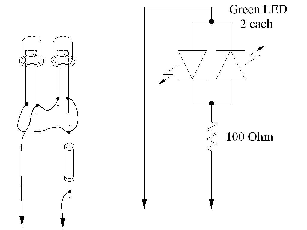
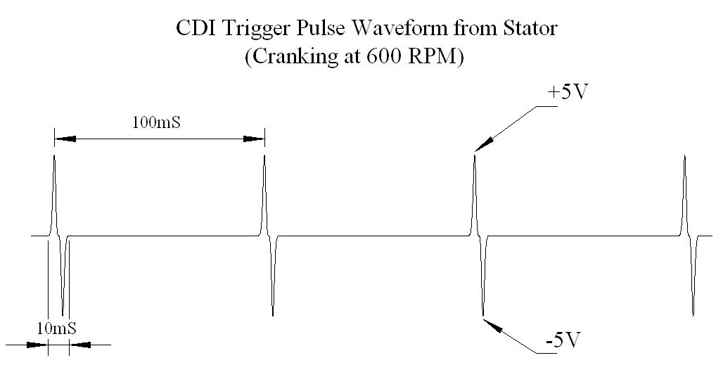
Here is the actual voltage waveform:
Any old LED pair will work, but you do need both of them. Both LED's must flash for the CDI to work. One LED is "Arm", the other LED is "fire".
The waveform shows the voltage (vertical axis) plotted against time (horizontal axis). Notice the sharp spikes followed by lots of zero volts in between. Meters sort of muddle through this averaging the change in voltage over a long period.
The other possibility is that something isn't being measured right, thus leading to wrong conclusions. Double and triple check those readings .
.
You have AC power to the CDI, you have a ground to the CDI, and youv'e eliminated the kill switch issues by disconnecting the kill switch wire at the CDI. You get no voltage at all at the CDI output. This suggests that the CDI is not being triggered, or the CDI and/or coil is defective. You've changed the CDI and the coil from a working quad.
This leads back to the CDI not getting triggered. You measured 0.3 volts AC before. This is what makes this a puzzler.
I don't know how much your soldering skills are, or how much access to electrical parts you have, but below is a simple test fixture for measuring the trigger pulse to the CDI, and a plot of the voltage you would see on a working quad with an oscilloscope. Remember that this is a waveform that isn't really measured correctly by most meters, but meters are often all that is available.
Here is an easy test fixture:
Here is the actual voltage waveform:
Any old LED pair will work, but you do need both of them. Both LED's must flash for the CDI to work. One LED is "Arm", the other LED is "fire".
The waveform shows the voltage (vertical axis) plotted against time (horizontal axis). Notice the sharp spikes followed by lots of zero volts in between. Meters sort of muddle through this averaging the change in voltage over a long period.
The other possibility is that something isn't being measured right, thus leading to wrong conclusions. Double and triple check those readings
.
Jun 6, 2011 | 11:59 PM
#17
Electrical Expert
Likes High Voltage In The Tub!
Likes High Voltage In The Tub!
Joined: Dec 2008
Posts: 3,260
Likes: 14
From: Tracy, California, USA
The trigger signal comes from the stator pickup coil which is mounted outside the flywheel. You already verified the wiring since you measured 110 ohms from the CDI trigger pin to ground. That resistance is the resistance of the trigger pickup coil through the wiring harness.
The trigger signal is generated by a raised bump on the flywheel that does a close "fly by" past the pickup coil. Inside the trigger coil is a magnet surrounded by a coil of wire. Around that is a permeable core that keeps the internal magnet's external field bottled up except for the small opening near where the raised bump passes by.
As the steel bump passes by it bends the magnet's field this way and that at the bumps edges, which cuts through the coil windings, and generates the +/- pair of pulse as shown in the earlier trigger waveform.
By putting the magnet inside the pickup coil, and keeping the external field from the magnet bottled up, the sensing "reach" of the pickup coil is severely limited to just a fraction of an inch. This is necessary to keep the other *huge* magnets inside the flywheel that form the battery charge section from influencing the timing pickup coil waveform.
So what else could be wrong with the pickup coil sense it is hooked properly and measures the right resistance?
1) A short between adjacent turns would kill any output signal without affecting the total resistance that much. No solution here but to change the pickup coil (often the whole stator is changed because that is what you have to buy).
2) A gap that is too large betwen the pickup coil and the raised bump on the flywheel will result in a trigger pickup signal that is too small to generate a spark. Some quads have adjustable gap, most do not. As a ballpark guideline, Eton quads specify that this gap be set to 0.025".
3) If magnetic debris in the stator area gets lodged in the pickup coil sense opening then the internal magnet gets magnetically bottled up even more, reducing the trigger signal substantially. Remember that the magnet inside the trigger coil will attract and hold magnetic clutter (rust particles, steel shavings, etc.), so it happens sometimes.
The confounding variable here is that you measured a 0.3 volt trigger signal which is normally good enough. Again meters don't measure this type of waveform well, and different meters measure differently. Some meters averge the AC voltage results over time, others detect the peak, others fall somewhere in between. The dual LED setup in the last post will absolutely resolve that issue. LED's don't conduct untill they get about 2 volts across them. Thus if the LED's light up you know they are seeing at least a two volts peak voltage during the trigger spike, which is more than enough to trigger the CDI.
Jun 13, 2011 | 07:02 PM
#18
Weekend Warrior
Joined: May 2011
Posts: 18
Likes: 0
OK, I built the Trigger Tester and both LEDs blink when cranking. I also retested everything else, here are the results:
Method 1) Unplug the CDI and remove the kill switch pin in the CDI connector on the wiring harness. The
pin is held in with a spring tab on the pin itself. You'll have to probe into the connector and push this
tab in order to extract the pin. Plug the CDI back in (kill switch wire dangling) and see if you have
spark. Used method 2 this time
Method 2) Unplug the CDI. Turn on the ignition switch and set all kill switches to the run position. Use a
meter to measure resistance in of the kill switch pin in the wiring harness connector to engine/frame
ground. If the reistance is infinite on the 100K ohm scale then your kill switches/kill switch wiring are
OK. If you measure zero ohms then you have a kill switch/wiring issue. jumping from 10 to 18
The other inputs your CDI needs to make spark are AC Ignition Power, and the Trigger signal. Do the
following:
1) Unplug the CDI. In the wiring connector measure the resistance of the AC Ignition Power pin to the
Ground pin. You should see 400 ohms or so. What do you measure? 527
2) Measure the resistance of the Timing/trigger pin to the ground pin. You should measure 150 ohms or so.
What do you measure? 115
3) Leave the CDI unplugged. Set your meter to measure AC volts on the 100 volt scale. Measure the voltage
on the AC Ignition Power pin to the ground pin while cranking the engine. You should see 40 to 80 volts AC
while the engine is cranking. What do you measure?
38 to 41
4) Set your meter to measure AC volts on the lowest scale you have. Ideally this would be 2 volts but many
meters don't go down this low. In that case use the lowest scale you have. Measure the voltage on the
Timing Trigger pin to the Ground pin while cranking the engine. You should 0.2 t0 0.4 volts AC. What do
you measure? .3 also both LEDs blinking on the trigger voltage tester.
Now for measuring the output side of the CDI:
A) Leave the CDI unplugged. In the CDI wiring connector measure the resistance of the Ignition Coil pin
to the ground pin. You should measure less than 1 ohm (but not zero ohms). What do you measure? 1.5
B) Plug the CDI back in. Set your meter to measure AC volts on the 20 volt scale. Set all kill switches
to the run position. Crank the engine while measuring the voltage on the Igntition Coil pin to ground.
Poke through the insulation of the wire if you can't probe the connector.
The lowest setting for voltage on my meter is 200. At that setting I am getting no reading, the meter stays at .1 and does not change.
Thanks,
Jeff
Jun 13, 2011 | 11:37 PM
#19
Electrical Expert
Likes High Voltage In The Tub!
Likes High Voltage In The Tub!
Joined: Dec 2008
Posts: 3,260
Likes: 14
From: Tracy, California, USA
My responses in red:
OK, I built the Trigger Tester and both LEDs blink when cranking. I also retested everything else, here are the results:
Method 1) Unplug the CDI and remove the kill switch pin in the CDI connector on the wiring harness. The
pin is held in with a spring tab on the pin itself. You'll have to probe into the connector and push this
tab in order to extract the pin. Plug the CDI back in (kill switch wire dangling) and see if you have
spark. Used method 2 this time
Method 2) Unplug the CDI. Turn on the ignition switch and set all kill switches to the run position. Use a
meter to measure resistance in of the kill switch pin in the wiring harness connector to engine/frame
ground. If the reistance is infinite on the 100K ohm scale then your kill switches/kill switch wiring are
OK. If you measure zero ohms then you have a kill switch/wiring issue. jumping from 10 to 18
10-18 what? I'm assuming 10-18K ohms (10,000 to 18,000 ohms). This is not right. This needs looking into further. The conflict here is that removing the kill switch pin right at the CDI (method 1) *will* make the resistance as seen by the CDI infinite - thus if kill switch issues were the problem removing the pin would have brought spark back. I would recheck method 1 again.
The other inputs your CDI needs to make spark are AC Ignition Power, and the Trigger signal. Do the
following:
1) Unplug the CDI. In the wiring connector measure the resistance of the AC Ignition Power pin to the
Ground pin. You should see 400 ohms or so. What do you measure? 527
2) Measure the resistance of the Timing/trigger pin to the ground pin. You should measure 150 ohms or so.
What do you measure? 115
I think you measured 514 and 110 ohms before for 1) and 2) above. This resistance varies a bit with temperature, so it still sounds OK
3) Leave the CDI unplugged. Set your meter to measure AC volts on the 100 volt scale. Measure the voltage
on the AC Ignition Power pin to the ground pin while cranking the engine. You should see 40 to 80 volts AC
while the engine is cranking. What do you measure?
38 to 41
This reading is low but I think it will make weak spark - not no spark. Is your starter spinning slow? The output voltage is directly proportional to engine speed.
4) Set your meter to measure AC volts on the lowest scale you have. Ideally this would be 2 volts but many
meters don't go down this low. In that case use the lowest scale you have. Measure the voltage on the
Timing Trigger pin to the Ground pin while cranking the engine. You should 0.2 t0 0.4 volts AC. What do
you measure? .3 also both LEDs blinking on the trigger voltage tester.
The blinking LED's prove that the trigger signal is adequate. You do not have a trigger problem.
Now for measuring the output side of the CDI:
A) Leave the CDI unplugged. In the CDI wiring connector measure the resistance of the Ignition Coil pin
to the ground pin. You should measure less than 1 ohm (but not zero ohms). What do you measure? 1.5
This still sounds high to me. You were swapping parts between quads. What about the other quad that works? Does this test measure 1.5 ohms on that quad too?
B) Plug the CDI back in. Set your meter to measure AC volts on the 20 volt scale. Set all kill switches
to the run position. Crank the engine while measuring the voltage on the Igntition Coil pin to ground.
Poke through the insulation of the wire if you can't probe the connector.
The lowest setting for voltage on my meter is 200. At that setting I am getting no reading, the meter stays at .1 and does not change.
Still sounds like the CDI is not getting triggered, or the output of the CDI is loaded down.
Thanks,
Jeff
Jun 17, 2011 | 01:21 PM
#20
Weekend Warrior
Joined: May 2011
Posts: 18
Likes: 0
Could this have anything to do with the brake lever? ( you have to pull the brake to start.)
Is there a way to bypass all the kill switches and/or safety switches?
Maybe wire up a push button or something?
Thanks for all the help,
Jeff
Is there a way to bypass all the kill switches and/or safety switches?
Maybe wire up a push button or something?
Thanks for all the help,
Jeff